Circulating type hydraulic oil tank structure and use method thereof

A hydraulic oil tank and hydraulic oil technology, which is applied in the direction of oil supply tank devices, fluid pressure actuation devices, fluid pressure actuation system components, etc., can solve the problem of reducing the service life of hydraulic components and oil, system collapse, and oil pollution, etc. problem, achieve the effect of reducing the chance of entering the fuel tank, cooling evenly and stably, and increasing the service life

Inactive Publication Date: 2014-12-10
CHENGDU XINGBODA PRECISION MACHINERY
View PDF0 Cites 2 Cited by
  • Summary
  • Abstract
  • Description
  • Claims
  • Application Information

AI Technical Summary

Problems solved by technology

[0003] In a harsh and highly polluted environment, outside air, water, dust and solid particles can easily enter the fuel tank, polluting the oil while reducing the service life of hydraulic components and oil, weakening the reliability of the hydraulic system, and causing hydraulic pressure System failure, which will cause the collapse of the entire system in severe cases
When the traditional hydraulic oil tank is working, humid air and dust will inevitably enter the oil tank through the filter. In addition, when the filter is replaced, the pollutants will inevitably be brought into the oil tank, and the distance between the partitions in the traditional hydraulic oil tank The oil return port is too close, so that the oil circulation distance is too short, and the oil does not have enough time to precipitate impurities, which eventually leads to a decrease in the overall amount of working fluid. New working fluid must be replenished in time, which reduces the circulation efficiency of the oil tank and also causes filtration The working strength of the device increases and the service life decreases

Method used


Image

  • Circulating type hydraulic oil tank structure and use method thereof

Examples


Embodiment 1

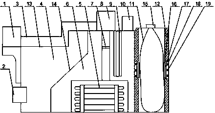
[0020] Such as figure 1As shown, the present invention is a circulating hydraulic oil tank structure and its use method. The high-temperature hydraulic oil enters the oil return chamber 6 through the oil guide pipe 3 after being cooled by the cooler 1 for the first time, and the sediment in the hydraulic oil is filtered It flows into the hydraulic oil cooler 15 under the filtering effect of the filter. Since the hydraulic oil still has a certain residual temperature in the first cooling, the residual heat will affect the transmission efficiency when the hydraulic oil enters the transmission parts. After the second cooling effect of the cooler 15, the liquid level of the hydraulic oil begins to rise in the oil return chamber 6; at this time, the volume change of the hydraulic oil in the oil tank needs to be realized by exchanging the gas with the external environment, but the external pollution The air bag 11 set in the oil return chamber 6 can return to the oil return chamber ...

Embodiment 2

[0022] Such as figure 1 As shown, this embodiment is based on Embodiment 1, and the tank body 13 is provided with an oil filling port 10 , and the oil filling port 10 communicates with the upper end of the oil return chamber 6 . In order to avoid the situation that the volume change of the air bag 11 is not enough to make up for the volume change in the oil return chamber 6 when the total amount of hydraulic oil in the oil tank is lower than the standard oil volume, an oil filling port 10 is provided on the tank body 13, and the oil filling port 10 is connected with the upper end of the oil return chamber 6, so that the staff can inject new hydraulic oil into the oil return chamber 6 in time to keep the pressure in the oil return chamber 6 stable and ensure the oil tank to circulate oil smoothly.

Embodiment 3

[0024] Such as figure 1 As shown, in this embodiment, on the basis of Embodiment 1, a magnetic filter screen 7 is installed in the oil return cavity 6, and the magnetic filter screen 7 is located between the hydraulic oil cooler 15 and the oil return filter 8 between. During the long-term working process of the hydraulic system, certain wear and tear will occur between the parts, and the fine debris generated by the wear will return to the oil return chamber 6 together with the hydraulic oil, which will damage the hydraulic system during repeated use. The working efficiency of the machine has a significant impact. The installed magnetic filter screen 7 can collect the metal debris generated, reduce the impact on the components in the hydraulic system, and improve the effect of hydraulic transmission.

[0025] As a preference, when the electric air valve is connected with the pressure sensor 17, it can more flexibly adjust the injection amount of air, and improve the working e...


PUM


Abstract

The invention discloses a circulating type hydraulic oil tank structure and a use method of the circulating type hydraulic oil tank structure. When the size of an airbag is increased constantly, the airbag acts on the inner wall of a cavity of the airbag, when stress of pressure sensors reaches a standard value, an air valve is controlled to reduce or stop air injection, and the situation that the airbag is broken due to overinflating is avoided. Due to the fact that the size of the airbag is changed fast, springs and baffles arranged in grooves can buffer stress of the airbag acting on the pressure sensors, and the service life of the pressure sensors is prolonged.

Description

technical field [0001] The invention relates to the field of hydraulic oil tanks, in particular to a circulating hydraulic oil tank structure and a method for using the same. Background technique [0002] The main functions of the oil tank in the hydraulic system are: 1. To store the oil required for the system circulation; 2. To dissipate the heat generated when the system works; 3. To release the gas mixed in the oil; The installation provides the location. The oil tank should remove the dirt deposited in the oil in time, and the oil in the oil tank must meet the cleanliness requirements of the hydraulic system. As an important part of the hydraulic system, the hydraulic oil tank can cool it in time in the cooling system of the working fluid, reduce the oxidation rate of the oil, and reduce the corrosion and wear of the hydraulic components. [0003] In a harsh and highly polluted environment, outside air, water, dust and solid particles can easily enter the fuel tank, p...

Claims


Application Information

Patent Timeline
IPC IPC(8): F15B1/26F15B21/04
Inventor 吴光武
Owner CHENGDU XINGBODA PRECISION MACHINERY
Why Eureka
Try Eureka