
A kind of crude oil transportation pipeline system and crude oil transportation method thereof

A technology for transporting pipelines and crude oil, applied in the crude oil transport pipeline system and the field of crude oil transport, can solve the problems of large transport energy consumption, lower crude oil temperature, and increased crude oil viscosity, avoid direct contact, reduce transport resistance, and reduce transport costs. Effect

Inactive Publication Date: 2017-01-04
CHINA UNIV OF PETROLEUM (EAST CHINA)
View PDF6 Cites 0 Cited by
  • Summary
  • Abstract
  • Description
  • Claims
  • Application Information

AI Technical Summary

Problems solved by technology

[0002] In the process of conventional crude oil transportation, the crude oil directly contacts the inner wall of the pipeline. Due to the high viscosity of crude oil, it often results in a large amount of transportation energy consumption.
And with the progress of the transportation process, the temperature of crude oil continues to decrease, and the viscosity of crude oil continues to increase, which in turn causes the energy consumption of crude oil transportation to increase continuously, and the cost of crude oil transportation continues to increase

Method used


Image

  • A kind of crude oil transportation pipeline system and crude oil transportation method thereof
  • A kind of crude oil transportation pipeline system and crude oil transportation method thereof
  • A kind of crude oil transportation pipeline system and crude oil transportation method thereof

Examples


Embodiment 1

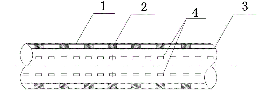
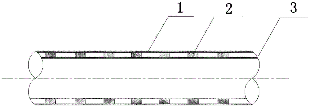
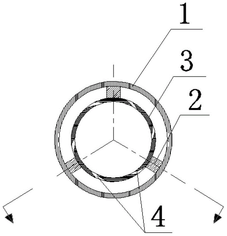
[0025] A crude oil transportation pipeline system, comprising an outer pipe 1 and an inner pipe 3, the inner pipe 3 is set inside the outer pipe 1, the inner pipe 3 is filled with crude oil, and a positioning block 2 is installed between the inner pipe 3 and the outer pipe 1, A closed cavity is formed between the inner tube 3 and the outer tube 1, and the high-pressure liquid filled in the cavity is a low-viscosity liquid that is easily obtained such as condensate oil or light oil or oilfield production water, and the pressure is 0.5MPa-15MPa.

[0026] There are a plurality of swirl holes 4 on the inner pipe wall from the outer surface to the inner surface. The swirl holes 4 are evenly distributed on the inner pipe wall. The ratio of the diameter of the swirl holes to the diameter of the inner pipe is 0.001-0.02, so as to form a uniform conveying medium layer. The swirl holes obliquely intersect with the inner pipe wall, and the included angles formed by each swirl hole and th...

Embodiment 2

[0033] A crude oil transportation pipeline system, including an outer pipe and an inner pipe, the inner pipe is set inside the outer pipe, the inner pipe is filled with crude oil, a positioning block is installed between the inner pipe and the outer pipe, and the inner pipe and the outer pipe form a The airtight cavity, the high-pressure gas that can also be filled in the cavity is an inert gas such as natural gas or nitrogen, and the pressure is 0.5MPa-15MPa.

[0034] There are multiple swirl holes on the inner pipe wall from the outer surface to the inner surface, and the swirl holes are evenly distributed on the inner pipe wall. The ratio of the diameter of the swirl holes to the diameter of the inner pipe is 0.001-0.02, so as to form a uniform conveying medium Floor. The swirl holes obliquely intersect with the inner pipe wall, and the included angles formed by each swirl hole and the tangent plane of the swirl hole inlet are consistent. The swirl hole connects the inner ...


PUM


Abstract

The invention discloses a crude oil transport pipeline system and a crude oil transport method thereof. The crude oil transportation pipeline system includes an outer pipe and an inner pipe. The inner pipe is set inside the outer pipe, the inner pipe is filled with crude oil, and a positioning block is installed between the inner pipe and the outer pipe to form a closed space between the inner pipe and the outer pipe. The cavity is filled with high-pressure liquid or high-pressure gas. There are a plurality of swirl holes on the inner tube wall from the outer surface to the inner surface, and the swirl holes connect the inner tube and the cavity. Based on the crude oil transportation method of this crude oil transportation pipeline, during the crude oil transportation process, the high-pressure liquid or high-pressure gas in the cavity forms a uniform and stable transportation medium layer on the inner wall surface of the inner pipe after passing through the swirl holes, wrapping the crude oil and avoiding The direct contact between the crude oil and the inner pipe reduces the transportation resistance of the crude oil and solves the problem of high energy consumption caused by the direct contact between the crude oil and the pipeline.

Description

technical field [0001] The invention relates to a crude oil transportation pipeline system and a crude oil transportation method thereof. Background technique [0002] In the process of conventional crude oil transportation, crude oil directly contacts the inner wall of the pipeline. Due to the high viscosity of crude oil, it often results in a large amount of transportation energy consumption. And with the progress of the transportation process, the temperature of crude oil continues to decrease, and the viscosity of crude oil continues to increase, which in turn causes the energy consumption of crude oil transportation to increase continuously, and the cost of crude oil transportation continues to increase. Contents of the invention [0003] In order to solve the deficiencies of the prior art, the present invention proposes a crude oil transportation pipeline system and its crude oil transportation method. The present invention takes necessary technical measures to reduc...

Claims


Application Information

Patent Timeline
Patent Type & Authority Patents(China)
IPC IPC(8): F17D1/16F16L9/14F16L55/00
Inventor 蒋文明刘杨边江石念军付法栋王英伟
Owner CHINA UNIV OF PETROLEUM (EAST CHINA)
Learn More