Fiber grating displacement meter based on spring and constant strength beam

A technology of equal-strength beams and fiber gratings, applied in the direction of using optical devices, measuring devices, instruments, etc., can solve the problems of low measurement accuracy and achieve the effect of improving accuracy

Inactive Publication Date: 2014-12-10
杭州珏光物联网科技有限公司
View PDF7 Cites 2 Cited by
  • Summary
  • Abstract
  • Description
  • Claims
  • Application Information

AI Technical Summary

Problems solved by technology

[0006] The purpose of the present invention is to provide a stable and accurate fiber grating displacement meter in order to overcome the problem of low measurement accuracy of the fiber grating displacement meter in the prior art

Method used


Image

  • Fiber grating displacement meter based on spring and constant strength beam
  • Fiber grating displacement meter based on spring and constant strength beam
  • Fiber grating displacement meter based on spring and constant strength beam

Examples


Embodiment Construction

[0021] specific implementation plan

[0022] The present invention will be further described below in conjunction with the accompanying drawings, but they do not constitute a limitation to the present invention, but are only examples to make the advantages of the present invention more clear and easy to understand.

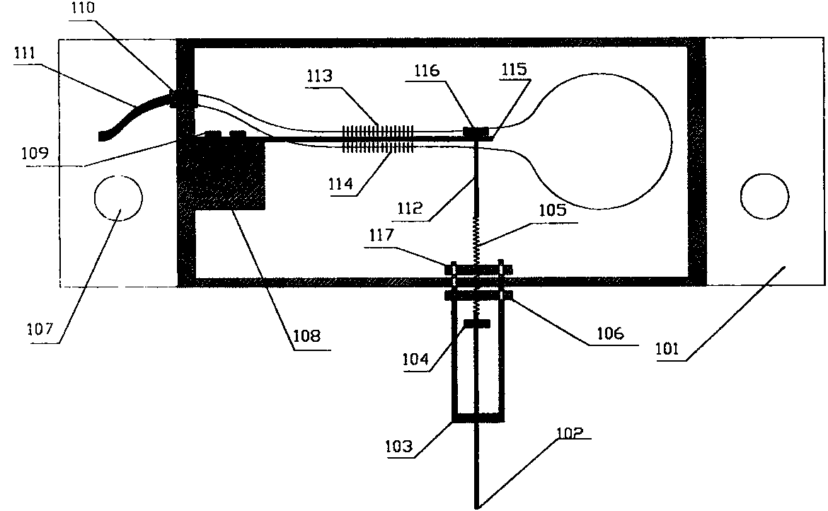
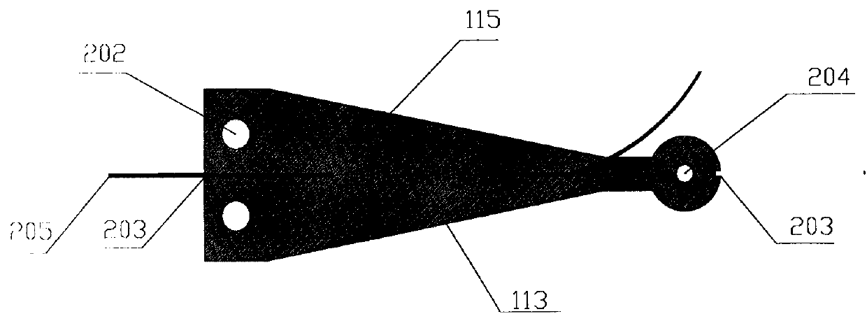
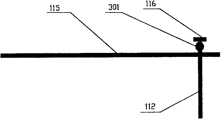
[0023] Such as figure 1 , figure 2 with image 3 As shown, the tail end of the equal-strength beam 115 is fixed to the housing 101 through the equal-strength beam fixing base 108 by using the equal-strength beam fixing screws 109, and the fiber gratings 113 and 114 pasted on the front and back sides of the equal-strength beam 115 pass through the housing 101 The armored optical cable 111 is introduced, and the armored optical cable 111 is fixed to the casing 101 by the cable sealing interface 110 to protect the optical fiber 205; There is a hollow steel ball 301 between the protrusions 116 of 115, the other end of the inner wire rope 112 is connected with the ...


PUM


Abstract

The invention relates to a fiber grating displacement meter based on a spring and a constant strength beam. The tail end of the constant strength beam is fixed to a housing through a beam holder, fiber gratings pasted to the two opposite sides of the constant strength beam pass the housing and are led into an armored cable; the armored cable is fixed to the housing through a cable sealing port to protect fibers; the stress bearing end of the constant strength beam is connected with one end of an inner wire rope; the other end of the inner wire rope is connected with the displacement spring which is connected with an outer wire rope; a limiter is arranged on the outer wire rope and is led out through a stay tube fixed to the housing. The fiber grating displacement meter has the advantages of high precision and good stability.

Description

Technical field: [0001] The invention belongs to the field of optical fiber sensing and relates to an optical fiber grating displacement meter. technical background [0002] In civil engineering, slope and other engineering fields, structural health monitoring is of great significance to the long-term operation of the project. At present, the measuring tools often used for the displacement and deformation of building structures are electronic sensors. Due to the poor performance of the electronic sensor itself in lightning resistance , Poor anti-electromagnetic interference performance, and short measurement distance, resulting in poor reliability, small measurement range, and low measurement accuracy. [0003] In 1978, K.O.Hill and others first used the standing wave writing method in germanium-doped optical fiber to make the first fiber grating. After more than 30 years of development, it has been widely used in optical fiber communication, optical fiber sensing and other ...

Claims


Application Information

Patent Timeline
Patent Type & Authority Applications(China)
IPC IPC(8): G01B11/02
Inventor 陈庆根王云鹏
Owner 杭州珏光物联网科技有限公司
Why Eureka
Try Eureka