Built-in light source brightness detection system and method

A technology with built-in light source and brightness detection, applied in the direction of using electric radiation detectors for light metering, etc., can solve the problems of small imaging brightness field of view, tedious calibration work, time-consuming, etc., to save calibration work and increase dynamic The effect of detection range

Active Publication Date: 2014-12-10
无锡市星迪仪器有限公司
View PDF5 Cites 2 Cited by
  • Summary
  • Abstract
  • Description
  • Claims
  • Application Information

AI Technical Summary

Problems solved by technology

The imaging luminance meter uses a two-dimensional array of photodetectors. In order to obtain the relationship between the radiation amount and the digital output under different exposure times, cumbersome calibration work is required, which is very time-consuming, and the field of view of the imaging luminance smaller

Method used


Image

  • Built-in light source brightness detection system and method
  • Built-in light source brightness detection system and method
  • Built-in light source brightness detection system and method

Examples


Embodiment Construction

[0035] The present invention will be further described below in conjunction with specific drawings and embodiments.

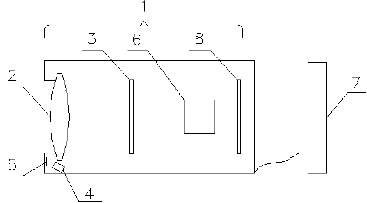
[0036] Such as figure 1 Shown: the luminance detection system of the built-in light source that the present invention proposes, comprises: optical imaging system 1, comprises imaging lens 2, optical filter 3, photodetector 6 that are arranged sequentially along incident optical path; And signal processing circuit 8; Signal processing The circuit 8 is used to generate and output video signals to the computer software processing module 7; the built-in light source 4 is fixed beside the imaging lens 2; The imaging lens 2 is focused on the imaging area of ​​the photodetector 6; the photodetector 6 is fixed on the focal plane of the imaging lens 2.

[0037] The imaging lens 2 can be a fixed focus lens or a zoom lens.

[0038] Described optical filter 3, curve is used for correcting the spectral response curve of photodetector 6, makes it match with the spectral re...


PUM


Abstract

The invention provides a built-in light source brightness detection system. The system comprises an optical imaging system, a built-in light source, a total reflection mirror and a computer software processing module. The optical imaging system comprises an imaging lens, a light filter, a photoelectric detector and a signal processing circuit, the imaging lens, the light filter and the photoelectric detector are arranged along an incident light path sequentially, and the signal processing circuit is used for generating and outputting a video signal. The built-in light source is fixed beside the imaging lens, the total reflection mirror is arranged in front of one side of the imaging lens and used for reflecting parallel beams emergent from the built-in light source into the imaging lens and focusing the parallel beams on the imaging area of the photoelectric detector, the photoelectric detector is fixed on a focal plane of the imaging lens, and a curve of the light filter is used for correcting a spectral response curve of the photoelectric detector. The computer software processing module is used for selecting imaging areas of a target and the built-in light source from an image after the image is acquired, and completes related gray acquisition and numeric calculation so as to calculate a brightness value of a target. The invention further provides a built-in light source brightness detection method utilizing the detection system.

Description

technical field [0001] The invention relates to a brightness detection device, in particular to a brightness detection system with a built-in light source and a corresponding brightness detection method. Background technique [0002] Brightness detection technology is a technology widely used in lighting engineering, traffic signals, light source design, film and television and other fields. The traditional luminance meter mainly uses a pair of light holes at a certain distance to receive the luminous flux of a fixed solid angle and a fixed projection area, so that it is not affected by the distance of the object. Generally, in order to aim at the object, some light splitting elements are often added to the optical system. Part of the light beam can be received by the human eye for aiming through the reflector and eyepiece, and the other part of the light beam still reaches the photodetector device to generate photoelectric conversion to achieve brightness measurement. This...

Claims


Application Information

Patent Timeline
Patent Type & Authority Applications(China)
IPC IPC(8): G01J1/42
Inventor 安宝林谢佳丽蔡实张立华方东
Owner 无锡市星迪仪器有限公司
Why Eureka
Try Eureka