Safety alarm for electrified parts of substation
A safety warning and alarm technology, which is applied in the direction of alarms, measuring current/voltage, and instruments that rely on interference with short-wavelength radiation, and can solve the problem of substation guardians or construction personnel who cannot intuitively obtain the safe distance of live equipment and safety accidents and other issues, to achieve the effect of wireless connection, convenient hanging, avoiding electric shock accidents, and reasonable matching
- Summary
- Abstract
- Description
- Claims
- Application Information
AI Technical Summary
Problems solved by technology
Method used
Image
Examples
specific Embodiment approach 1
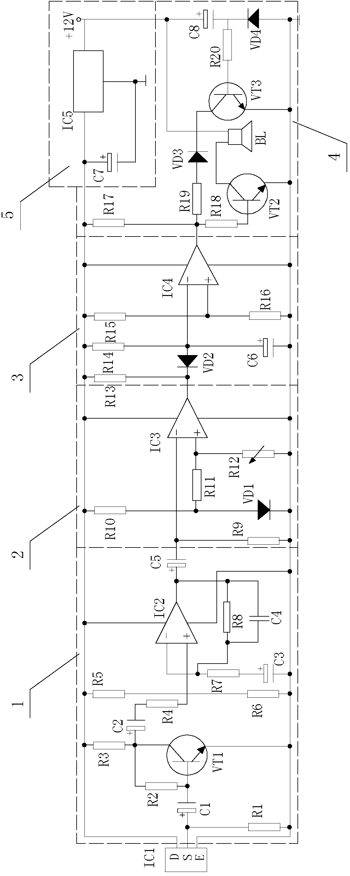
[0017] Specific implementation mode one: the following combination figure 1 Describe this embodiment mode, the substation described in this embodiment mode uses the safety warning alarm of live part, and described alarm device is arranged on the live equipment, and it comprises infrared sensor IC1, and it also comprises signal amplifying circuit 1, voltage comparator 2, alarm delay Timing circuit 3 and audio alarm circuit 4,
[0018] Infrared sensor IC1 is used to collect human body infrared signals within the preset safety threshold, the electrical signal output terminal of infrared sensor IC1 is connected to the electrical signal input terminal of signal amplifying circuit 1, and the amplified signal output terminal of signal amplifying circuit 1 is connected to voltage comparator 2 The voltage comparison signal input end of the voltage comparator 2, the voltage comparison signal output end of the voltage comparator 2 is connected to the delay signal input end of the alarm d...
specific Embodiment approach 2
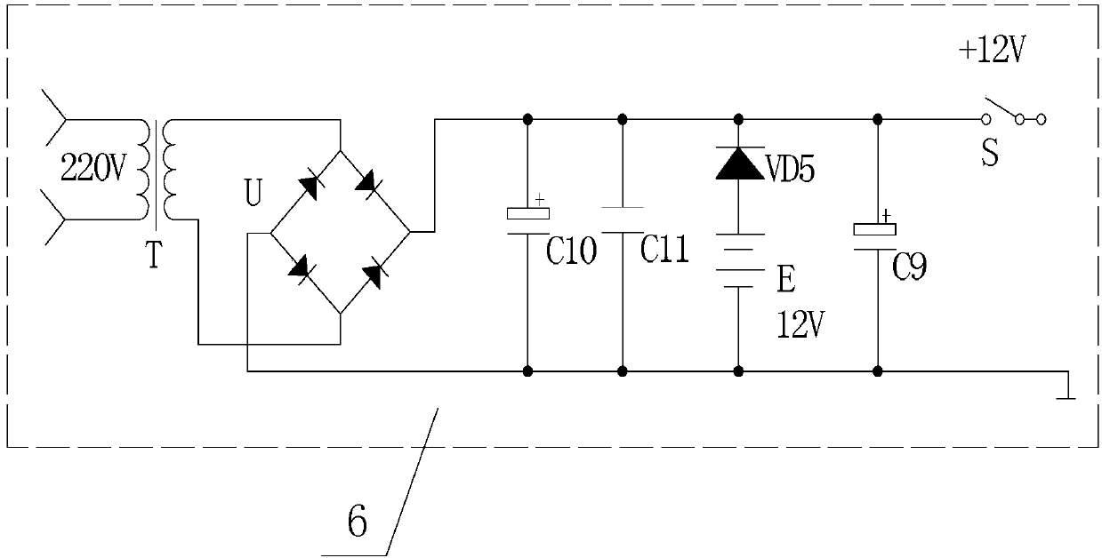
[0019] Specific implementation mode two: the following combination figure 1 and figure 2 Describe this embodiment, this embodiment will further describe the first embodiment, this embodiment also includes a voltage conversion circuit 5 and a power supply circuit 6,
[0020] The power supply circuit 6 is used to convert the power frequency 220V power supply into a DC 12V voltage output. After the DC 12V voltage is converted into a DC 6V voltage by the voltage conversion circuit 5, it becomes an infrared sensor IC1, a signal amplifier circuit 1, a voltage comparator 2, and an alarm delay. Time circuit 3 and audio alarm circuit 4 provide working power.
specific Embodiment approach 3
[0021] Specific implementation mode three: the following combination figure 1 and figure 2 Describe this embodiment, this embodiment will further explain Embodiment 2, the signal amplifying circuit 1 of this embodiment is composed of electrolytic capacitor C1, electrolytic capacitor C2, electrolytic capacitor C3, capacitor C4, electrolytic capacitor C5, resistor R1, resistor R2, Resistor R3, resistor R4, resistor R5, resistor R6, resistor R7, resistor R8, NPN transistor VT1 and operational amplifier IC2; voltage comparator 2 consists of resistor R9, resistor R10, resistor R11, variable resistor R12, diode VD1 and Operational amplifier IC3 is composed; alarm delay circuit 3 is composed of resistor R13, resistor R14, resistor R15, resistor R16, diode VD2, electrolytic capacitor C6 and operational amplifier IC4; audio alarm circuit 4 is composed of resistor R17, resistor R18, resistor R19, resistor R20, diode VD3, diode VD4, NPN transistor VT2, NPN transistor VT3, electrolytic ...
PUM
 Abstract
Description
Claims
Application Information
 - R&D
- Intellectual Property
- Life Sciences
- Materials
- Tech Scout
- Unparalleled Data Quality
- Higher Quality Content
- 60% Fewer Hallucinations
Browse by: Latest US Patents, China's latest patents, Technical Efficacy Thesaurus, Application Domain, Technology Topic, Popular Technical Reports.
© 2025 PatSnap. All rights reserved.Legal|Privacy policy|Modern Slavery Act Transparency Statement|Sitemap|About US| Contact US: help@patsnap.com


