Stator of reluctance resolver and reluctance resolver
A rotary transformer and reluctance technology, applied in the field of transformers, can solve problems such as low product reliability and extremely high requirements for winding production technology, reduce the number of winding operations, reduce insulation damage and cause short circuits, and simplify the winding process Effect
- Summary
- Abstract
- Description
- Claims
- Application Information
AI Technical Summary
Problems solved by technology
Method used
Image

Examples
specific Embodiment 1
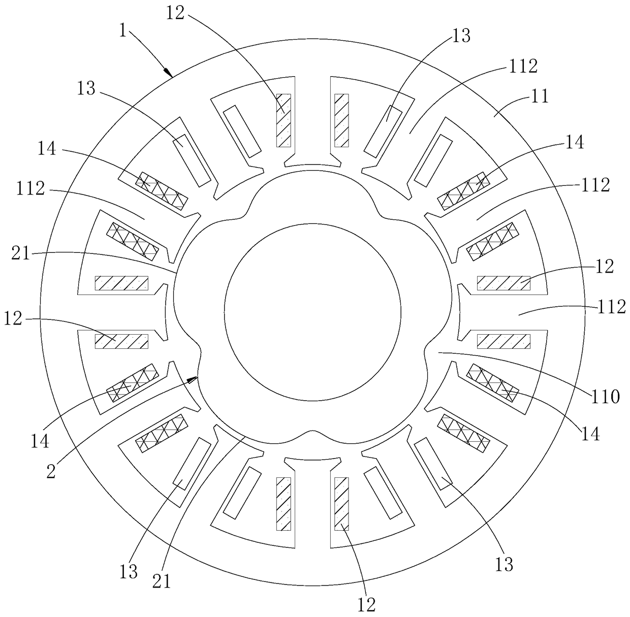
[0026] Such as figure 1 and figure 2 As shown, as a specific embodiment 1 of the present invention, the excitation winding is wound on one-third of the stator teeth 112 and an excitation coil 12 is formed on each of the one-third of the stator teeth 112, that is, the excitation The number of coils 12 is one-third of the number of stator teeth 112 , two stator teeth 112 are spaced between any two adjacent excitation coils 12 , and the winding directions of any two adjacent excitation coils 12 are the same. In this embodiment, each excitation coil 12, sine output coil 13, and cosine output coil 14 are respectively wound on different stator teeth 112, thereby realizing completely separate winding of the excitation winding, sine output winding, and cosine output winding, and Since the coil turns of the two output windings are constant values, it can simplify the winding process, improve the product yield and improve product quality and reliability under the premise of ensuring ...
Embodiment 2
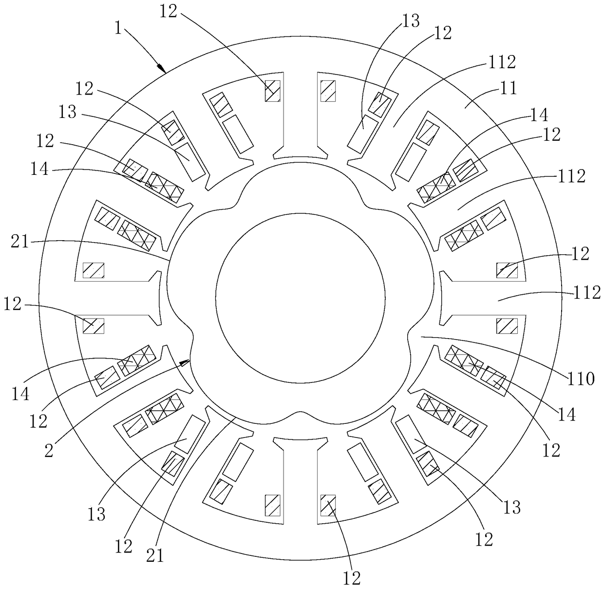
[0049] Such as image 3 As shown, as the second specific embodiment of the present invention, the field windings are wound on all the stator teeth 112 and an field coil 12 is respectively formed on each stator tooth 112, that is, the number of field coils 12 is the same as the number of stator teeth 112 Each excitation coil 12 is wound on each stator tooth 112 respectively, and the winding directions of any two adjacent excitation coils 12 are opposite. In this embodiment, an excitation coil 12 is wound on each stator tooth 112. Since the output winding coils of two different phases, the sine output coil 13 and the cosine output coil 14, are wound on different stator teeth 112, therefore , the same stator tooth 112 will be wound with at most an input winding coil and an output winding coil at the same time, and there will be no situation where two output winding coils of different phases are wound on the same stator tooth 112, which satisfies On the premise of meeting the des...
Embodiment 3
[0057] Such as Figure 4 As shown, as the third specific embodiment of the present invention, the number of excitation coils 12 is one-half of the number of stator teeth 112, and each excitation coil 12 is respectively wound on each odd-numbered tooth or each even-numbered tooth, and any adjacent The winding directions of the two excitation coils 12 are the same. In this embodiment, the number of excitation coils 12 is half of the number of stator teeth 112 , and there is a stator tooth 112 between any two adjacent excitation coils 12 . In this embodiment, the exciting coils 12 are wound on all odd-numbered teeth or even-numbered teeth. Since the output winding coils of two different phases, the sine output coil 13 and the cosine output coil 14, are wound on different stator teeth 112, Therefore, the same stator tooth 112 can at most be wound with an input winding coil and a kind of output winding coil at the same time, and there will be no situation where two output winding ...
PUM
 Abstract
Description
Claims
Application Information
 - R&D
- Intellectual Property
- Life Sciences
- Materials
- Tech Scout
- Unparalleled Data Quality
- Higher Quality Content
- 60% Fewer Hallucinations
Browse by: Latest US Patents, China's latest patents, Technical Efficacy Thesaurus, Application Domain, Technology Topic, Popular Technical Reports.
© 2025 PatSnap. All rights reserved.Legal|Privacy policy|Modern Slavery Act Transparency Statement|Sitemap|About US| Contact US: help@patsnap.com