Apparatus for extracorporeal treatment of blood

A technology for extracorporeal blood processing and blood, which is used in blood filtration, other medical devices, suction devices, etc.

Active Publication Date: 2014-12-10
GAMBRO LUNDIA AB
View PDF14 Cites 3 Cited by
  • Summary
  • Abstract
  • Description
  • Claims
  • Application Information

AI Technical Summary

Problems solved by technology

[0006] - how long these patients will suffer from renal insufficiency is unknown; thus, the tota

Method used


Image

  • Apparatus for extracorporeal treatment of blood
  • Apparatus for extracorporeal treatment of blood
  • Apparatus for extracorporeal treatment of blood

Examples


example 1

[0212] Figure 5 A first example of implementation of the control process already described herein above is shown.

[0213] In this embodiment, the control process includes:

[0214] - determined at the detection point T i previous time period T retro The value of the fluid removed from the patient within V pfr_removed ;

[0215] - determined at the detection point T i After the time period T prosp The value V of the fluid to be removed from the patient within pfr_need , so that at the detection point T i previous time period T retro and detection point (T i ) after the time period T prosp The total time period fluid withdrawal rate Q pfr The setting value of Q pfr_set ;exist Figure 5 middle, T retro equal to T prosp : Of course this can be the preferred choice, it should be noted that T retro can also be used with T prosp different.

[0216] - Setpoint Q based on fluid withdrawal rate pfr_set , at the detection point (T i ) after the time period T prosp ...

example 2

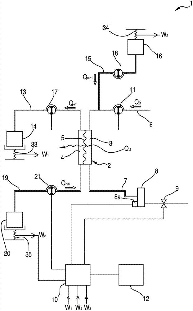
[0239] Image 6 A second example of implementation of the control process already described herein above is shown.

[0240] In this case, the process is aimed at achieving the most accurate removal of patient fluid within a predefined period of time. In this example, a number of time periods of constant duration ΔT are preset, starting at a preset time T00:

[0241] T 00 ; T 00 +ΔT;...;T 00 +k·ΔT

[0242] and end at the preset end time

[0243] T 00 +ΔT; T 00 +2ΔT;...;T 00 +(k+1)·ΔT.

[0244] In this variant, the purpose of the control unit 10 is to deliver precise indications of patient fluid removal within predefined time windows, for example to match staff shifts or simply "on the hour" (13:00, 14:00, 15:00, ...).

[0245] When calculating the instantaneous Q pfr_new , the "detection point T" can be completed in the following manner i ":

[0246] - at each processing interruption (downtime);

[0247] - at each flow setting change;

[0248] - at each predefin...

example 3

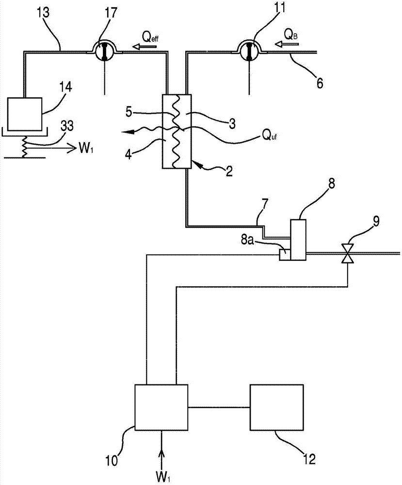
[0283] The following example is the same as example 2 (refer to image 3 with Image 6 ) similarly, showing the effective part T eff The calculation and use of , in this case by taking the detection point T i The effective fraction T is determined by reducing the duration of the subsequent time period by a first amount associated with the average bag change time expected to be spent in the following time period and by a second amount associated with downtime due to the alarm condition eff .

[0284] Apply algorithm (6) to image 3 means, assuming:

[0285] - The operator initially sets Q pfr_set =100ml / h;

[0286] - Predefined time windows: 0:00; 4:00; 8:00; 12:00; 16:00; 20:00;

[0287] - detection time T i :10:30;

[0288] - Fluid actually taken out in [4:00; 8:00] measured by scale 33 is V pfr(k-1) = 396ml;

[0289] - Fluid actually taken out in [4:00; 10:30] measured by scale 33 is V pfr(0) =245ml;

[0290] - The number of bag changes planned in [10:30; 12:00]...


PUM


Abstract

An apparatus for extracorporeal treatment of blood (1) comprising a filtration unit (2), a blood withdrawal line (6), a blood return line (7), an effluent fluid line (13), a pre and/or post-dilution fluid line (15, 25) connected to the blood withdrawal line, and a dialysis fluid line. Pumps (17, 18, 21, 22, 27) act on the fluid lines for regulating the flow of fluid. A control unit (10) is configured to periodically calculate a new value for the patient fluid removal rate to be imposed on an ultrafiltration actuator in order to keep a predefined patient fluid removal rate across a reference time interval irrespective of machine down times.

Description

technical field [0001] The invention relates to an extracorporeal blood treatment device. Background technique [0002] Extracorporeal blood treatment involves removing blood from a patient, treating the blood outside the patient, and returning the treated blood to the patient. Typically, extracorporeal blood treatment is used to extract undesirable substances or molecules from a patient's blood and to add desirable substances or molecules to the blood. Extracorporeal blood treatment is used for patients who cannot effectively remove substances from their blood, for example when the patient suffers from temporary or permanent kidney failure. These and other patients may undergo extracorporeal blood treatment to add substances to or remove substances from their blood, for example, to maintain acid-base balance or to remove excess body fluid. [0003] Extracorporeal blood treatment is usually accomplished by, for example, removing blood from a patient in a continuous flow, d...

Claims


Application Information

Patent Timeline
IPC IPC(8): A61M1/16A61M1/34
CPCA61M2205/3393A61M1/34A61M1/3434A61M1/1643A61M1/3431A61M2205/3334A61M1/1647A61M1/16A61M1/3413A61M1/341A61M1/3441A61M1/3451A61M2205/502A61M1/1605A61M1/361A61M1/3403A61M2205/18A61M2205/505A61M2205/52A61M1/3638
Inventor 多米尼克·普丘林
Owner GAMBRO LUNDIA AB
Why Eureka
Try Eureka