Metal connecting plate of a chain link of an energy chain

A technology of metal connecting plate and energy guide chain, applied in the field of energy guide chain, can solve the problems of high manufacturing cost and the like

Active Publication Date: 2014-12-10
椿本缆线牵引有限公司
View PDF9 Cites 4 Cited by
  • Summary
  • Abstract
  • Description
  • Claims
  • Application Information

AI Technical Summary

Problems solved by technology

The manufacturing cost of this energy guide chain is relatively large, because many parts have to be assembled with each other

Method used


Image

  • Metal connecting plate of a chain link of an energy chain
  • Metal connecting plate of a chain link of an energy chain
  • Metal connecting plate of a chain link of an energy chain

Examples


Embodiment Construction

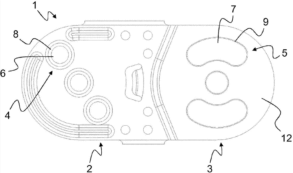
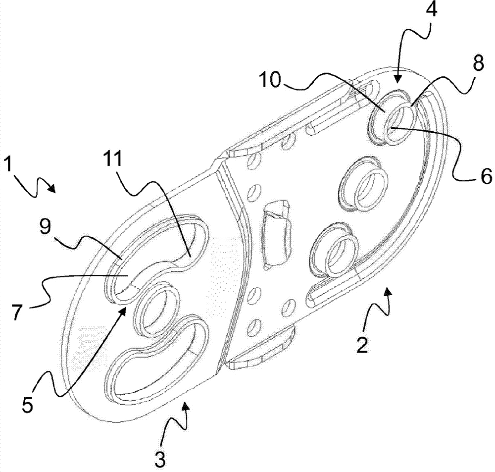
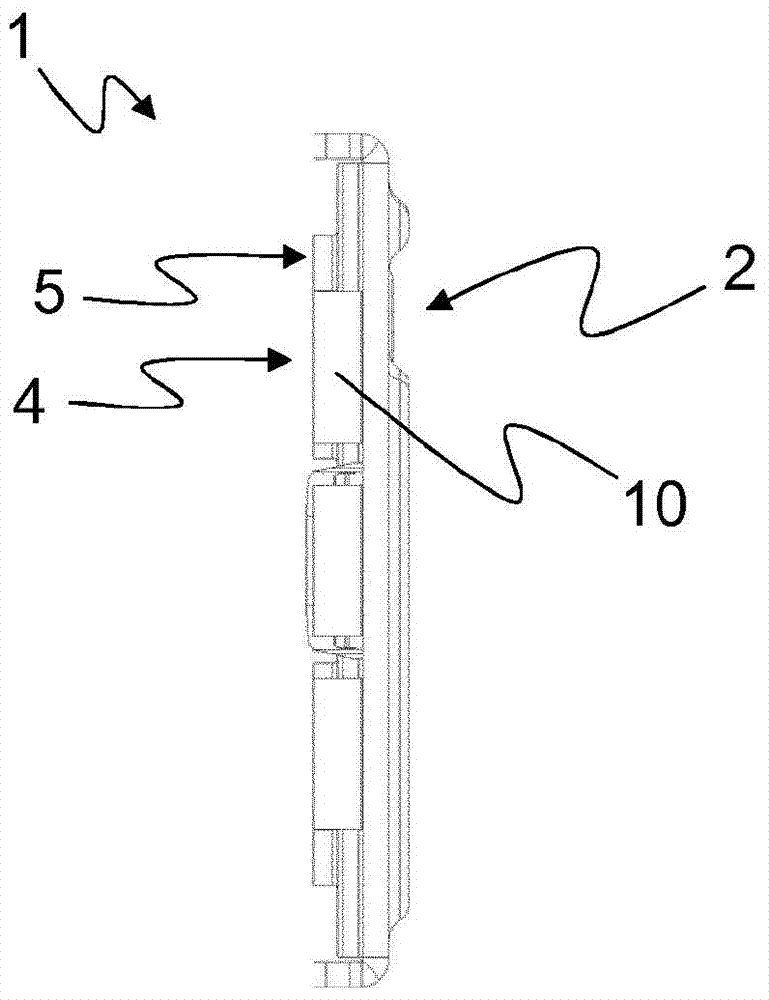
[0049] figure 1 A plan view of an embodiment variant of a metal web 1 is shown, wherein the first end 2 is shown on the left in the illustration and the second end 3 is shown on the right in the illustration. In this embodiment variant of the metal web 1 , two first elements 4 are provided at the first end 2 , which can be introduced into the second end of another structurally identical metal web 1 . part 3 in the kidney-shaped second element 5 . For greater clarity, only one of the elements is provided with a reference sign in each case. The first element 4 has a first bore 6 with a first flange 8 . It should be noted here that the flange 8 of the first hole 6 extends (substantially) perpendicularly to the metal web 1 . On the second end 3 there is a second kidney-shaped element 5 which has a second bore 7 with a second collar 9 . The second element 5 is intended to receive the first element 4 , thereby enabling rotation between two interconnected metal webs 1 inside the ...


PUM


Abstract

The invention relates to a metal connecting plate (1) of a chain link of an energy chain, which metal connecting plate has two ends (2, 3), wherein one end (2) has first elements (4) and the other end (3) has second elements (5), wherein the first elements (4) can be inserted into the second elements (5) of a further connecting plate (1) in such a way that the connecting plates (1) are rotatably connected to each other. The first and second elements (4, 5) are each formed by a hole (6, 7) having a border (8, 9). The borders (8, 9) form stop surfaces (10, 11) corresponding to each other, which stop surfaces protrude substantially perpendicularly to an extent of the connecting plate (1).

Description

technical field [0001] The invention relates to a metal connecting plate of a chain link of an energy guiding chain, a chain link of an energy guiding chain and an energy guiding chain. Background technique [0002] In order to guide lines, hoses, pipes or the like between fixed and movable connection points, so-called power chains are used. Leading or transporting energy, consumables or the like to the point of consumption via lines. The movable consumer can be, for example, a slide of a machine tool. [0003] It is known that energy-conducting chains can be produced from plastic. Such plastic energy guide chains are limited in their fields of use. Such limitations may arise from the weight and / or flexibility of the lines, hoses or the like to be guided. In special applications, the weight of the lines is so great that it exceeds the load-carrying capacity of the plastic energy guide chain. Furthermore, the use of energy guide chains made of plastic may be limited by e...

Claims


Application Information

Patent Timeline
Patent Type & Authority Applications(China)
IPC IPC(8): F16G13/16
CPCH02G11/006F16G13/16F16G15/14
Inventor T·阿梅斯S·恩格尔M·道布S·克拉泽克U·瓦格纳
Owner 椿本缆线牵引有限公司
Why Eureka
Try Eureka