Workpiece clamping device and workpiece clamping method for cylindrical grinding machine

A cylindrical grinding machine and workpiece clamping technology, applied in the field of grinding and processing fixtures, can solve the problems of inconvenient clamping, difficult to ensure the coaxiality between the clamping axis and the workpiece axis, and low clamping efficiency, and achieve high clamping efficiency. , Simple structure, convenient clamping effect

Inactive Publication Date: 2014-12-17
余姚市锋利电动工具厂(普通合伙)
View PDF8 Cites 11 Cited by
  • Summary
  • Abstract
  • Description
  • Claims
  • Application Information

AI Technical Summary

Problems solved by technology

[0003] The purpose of the present invention is to overcome the shortcomings of the current workpiece clamping device of the cylindrical grinding machine that the coaxiality between the clamping axis and the workpiece axis is difficult to ensure, the clamping is inconvenient and t

Method used


Image

  • Workpiece clamping device and workpiece clamping method for cylindrical grinding machine
  • Workpiece clamping device and workpiece clamping method for cylindrical grinding machine

Examples


Embodiment Construction

[0018] The present invention will be further described below in conjunction with the accompanying drawings.

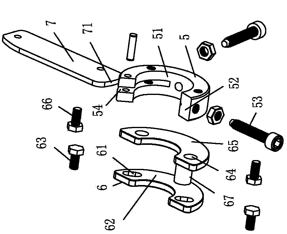
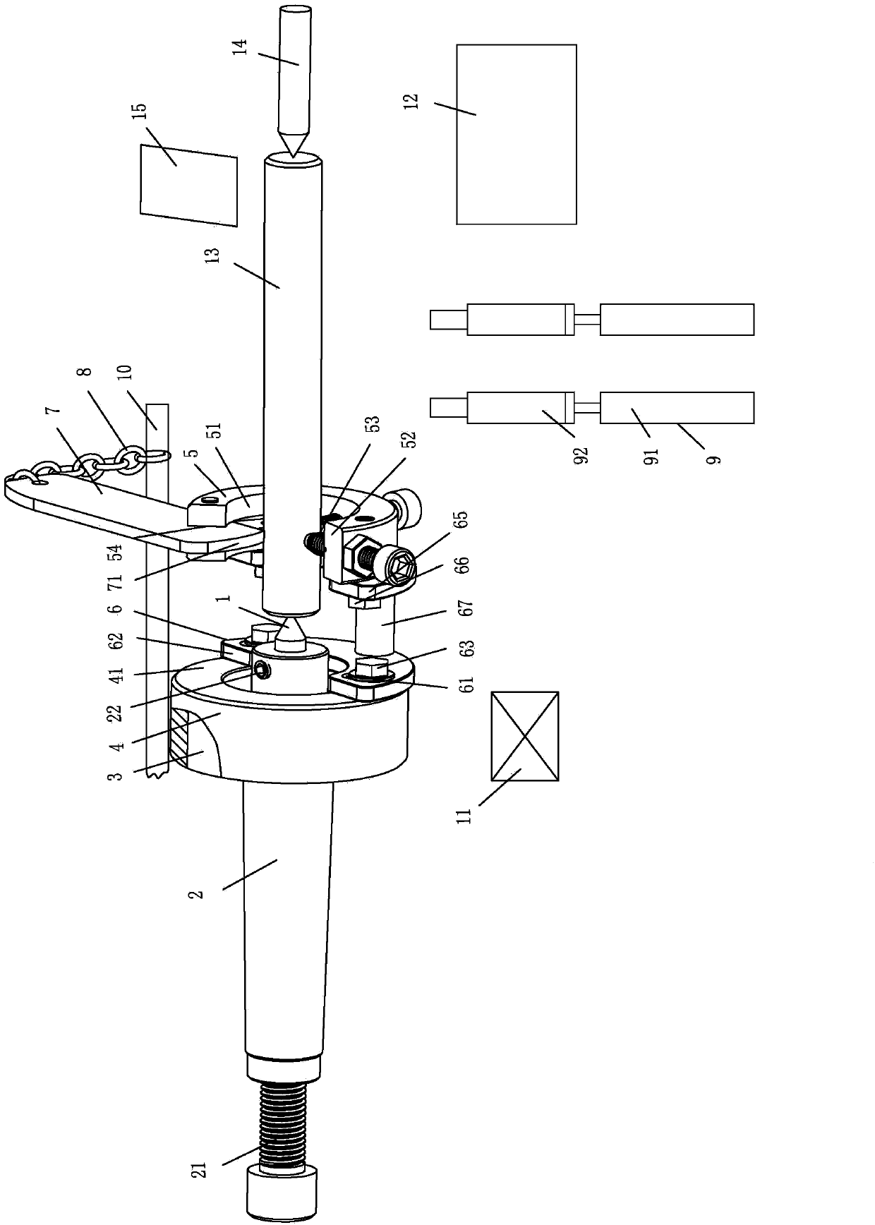
[0019] as attached figure 1 , attached figure 2 Shown: a workpiece clamping device for a cylindrical grinder, including a connecting handle 2 with a center hole (not shown in the drawings) at the front end, a headstock center point 1 whose rear end is located in the center hole, and is sleeved on the connecting handle 2 The one-way bearing 3 whose outer and inner rings are keyed to the connecting handle 2 is provided with a front retaining ring 41 and a bearing housing 4 connected with the outer ring of the one-way bearing 3, and a middle hole 51 is provided and is connected with the outer circumference and the middle hole respectively. The workpiece holder 5 of the opening 52 through which 51 penetrates, the adjustment assembly 6 connected to the workpiece holder 5 and the front retaining ring 41 respectively, and the inner end is provided with a clamp that clamps t...


PUM

PropertyMeasurementUnit
Central angleaaaaaaaaaa

Abstract

The invention relates to the field of a grinding fixture, aiming at providing a workpiece clamping device and a workpiece clamping method for a cylindrical grinding machine. The workpiece clamping device for the cylindrical grinding machine comprises a connecting handle, a headstock center, a one-way bearing, a bearing seat, a workpiece clamping body, an adjusting component, a clamping toggle piece, a toggle piece opening stay rope, a deflector rod position sensor and a controller, wherein the front end of the connecting handle is provided with a center hole; the rear end of the headstock center is arranged in the center hole; an inner ring of the one-way bearing is connected with the connecting handle in a transmission way; the bearing seat is provided with a front check ring and is connected with an outer ring of the one-way bearing; the workpiece clamping body is provided with a middle hole and an opening; the adjusting component is respectively connected with the workpiece clamping body and the front check ring; the clamping toggle piece is provided with a clamping arc surface at the inner end and is articulated with the opening side end; a plurality of clamping adjusting screws which are distributed along the circumference are arranged at the side periphery of the workpiece clamping body; the two ends of the toggle piece opening stay rope are respectively connected with the outer end of the clamping toggle piece and a deflector rod of the cylindrical grinding machine. After the workpiece clamping device for the cylindrical grinding machine is used, the coaxiality between the clamping axis and the workpiece axis can be maintained, clamping is conveniently carried out, and the clamping efficiency is higher.

Description

technical field [0001] The invention relates to the field of grinding fixtures, in particular to a workpiece clamping device and a workpiece clamping method for an outer cylindrical grinder. Background technique [0002] Pneumatic (hydraulic) dynamic chucks are commonly used in cylindrical grinders as the workpiece clamping device to cooperate with the top to clamp the workpiece, which has the disadvantage that the coaxiality between the clamping axis and the workpiece axis is difficult to guarantee; Chinese patent application number: utility model disclosure of CN 201120209154.3 Provided is a universal chuck device for cylindrical grinding machines, comprising a symmetrically arranged first clamping block and a second clamping block, the left and right ends of the first clamping block and the second clamping block are respectively provided with Adjusting bolts and fastening bolts, the first clamping block and the second clamping block are connected by adjusting bolts and fa...

Claims


Application Information

Patent Timeline
IPC IPC(8): B24B41/06
CPCB24B5/04B24B41/062
Inventor 王欢江
Owner 余姚市锋利电动工具厂(普通合伙)
Why Eureka
Try Eureka