Piston pin clamp spring press-fitting device

A press-fitting device and piston pin technology, applied in hand-held tools, manufacturing tools, etc., can solve problems such as slippage, high labor intensity of workers, and collapsing springs

Inactive Publication Date: 2014-12-17
ANHUI JIANGHUAI AUTOMOBILE GRP CORP LTD
View PDF8 Cites 9 Cited by
  • Summary
  • Abstract
  • Description
  • Claims
  • Application Information

AI Technical Summary

Problems solved by technology

However, this installation method is manual press-fitting, the work efficiency is low, and the labor intensity of the staff is high, and the press-fitting quality cannot be guaranteed; and the needle-nose pliers often slip when clamping the circlip, causing the circlip to collapse. cause personal injury

Method used


Image

  • Piston pin clamp spring press-fitting device
  • Piston pin clamp spring press-fitting device
  • Piston pin clamp spring press-fitting device

Examples


Embodiment Construction

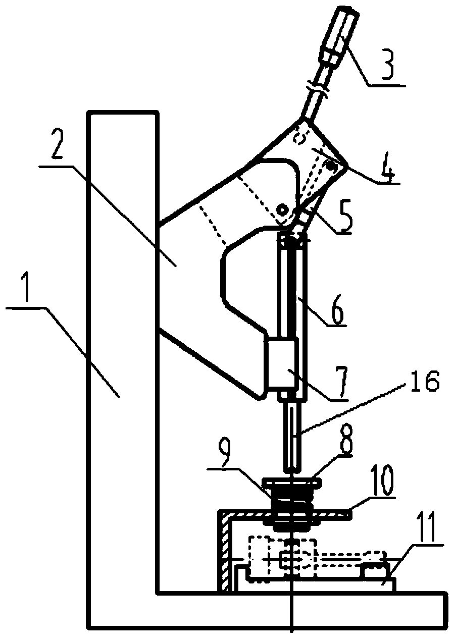
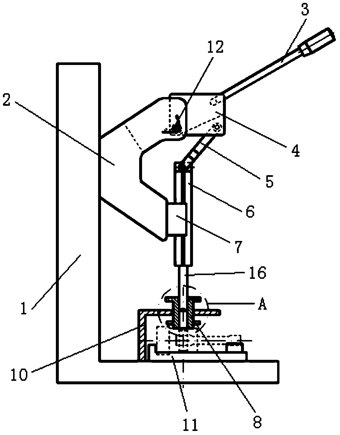
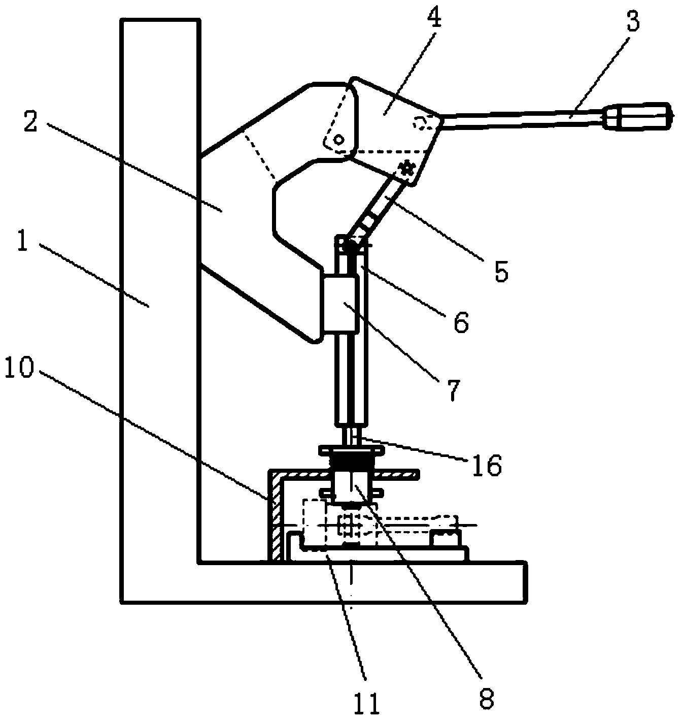
[0027] The core of the present invention is to provide a piston pin circlip press-fitting device, which can provide auxiliary press-fitting when manually installing the circlip, thereby improving the press-fitting efficiency and reducing the labor intensity of the staff; Slippage occurs during installation, which improves safety during installation.

[0028] In order to enable those skilled in the art to better understand the technical solutions of the present invention, the present invention will be further described in detail below in conjunction with the accompanying drawings.

[0029] Please refer to Figure 1 to Figure 5 , figure 1 Schematic diagram of the structure of the piston pin circlip pressing device provided by the present invention when it is at the upper limit position in a specific embodiment; figure 2 for figure 1 The schematic diagram of the structure of the piston pin circlip pressing device shown in the neutral position; image 3 for figure 1 The sche...


PUM


Abstract

The invention discloses a piston pin clamp spring press-fitting device, which comprises an L-shaped base, wherein a rotating element is hinged to a longitudinal part of the L-shaped base, one end of the rotating element is provided with a handle, the other end of the rotating element is hinged to a press rod, a guide frame and a piston connecting rod assembly frame are arranged on the transverse part, vertical to the longitudinal part, of the L-shaped base, a guide block is arranged on the guide frame, a guide hole is formed in the axial direction of the guide block, the hole diameter of the guide hole is smaller than the outer diameter of a clamp spring in the natural state, and is greater than the outer diameter of the clamp spring in the compression limit state, the outer diameter of the press rod is smaller than the hole diameter of the guide hole, and the axial direction of the press rod is over against the guide hole and approaches to or leaves away from the guide hole in the axial direction. Therefore the auxiliary press-fitting effect can be provided during the manual installation of the clamp spring through the piston pin clamp spring press-fitting device, so the press-fitting efficiency is improved, and the labor intensity of workers is reduced. Meanwhile, the clamp spring is prevented from slipping and disengaging in the installing process, and the safety during the installation is improved.

Description

technical field [0001] The invention relates to the technical field of auxiliary installation mechanisms for engine parts, in particular to a piston pin circlip pressing device. Background technique [0002] The piston connecting rod assembly of the engine includes a piston assembly, a connecting rod assembly, a piston pin and a snap ring. The connecting rod assembly and the piston assembly are connected together through the piston pin. It will not come out during exercise. The circlip is a kind of circular elastic part with an opening. When installing, it needs to use external force to make the diameter of the circlip smaller. At present, the press-fitting of the piston pin circlip mainly relies on the staff to use needle-nose pliers to clamp the circlip to make its diameter smaller, and then put it at the installation position. This manual press-fitting method is used to complete. However, this installation method is manual press-fitting, the work efficiency is low, and ...

Claims


Application Information

Patent Timeline
Patent Type & Authority Applications(China)
IPC IPC(8): B25B27/02
CPCB25B27/02
Inventor 张玉龙赵贺金张亮王东鑫闫浩泉李婷
Owner ANHUI JIANGHUAI AUTOMOBILE GRP CORP LTD
Why Eureka
Try Eureka