Multilink rear axle for a motor vehicle

A rear axle, multi-link technology, applied in the direction of vehicle springs, vehicle components, interconnection systems, etc., can solve problems such as the inability to realize the driving dynamic characteristics of trailing arm axles, and achieve improved effectiveness and increased roll stability. Effect

Active Publication Date: 2014-12-17
FORD GLOBAL TECH LLC
View PDF14 Cites 10 Cited by
  • Summary
  • Abstract
  • Description
  • Claims
  • Application Information

AI Technical Summary

Problems solved by technology

However, the known driving dynamics of eg trailing arm axles cannot be achieved with this simple construction

Method used


Image

  • Multilink rear axle for a motor vehicle
  • Multilink rear axle for a motor vehicle
  • Multilink rear axle for a motor vehicle

Examples


Embodiment Construction

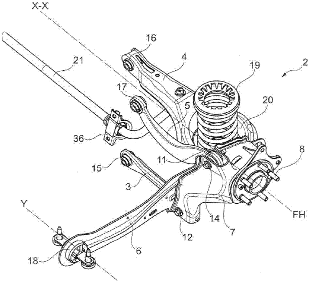
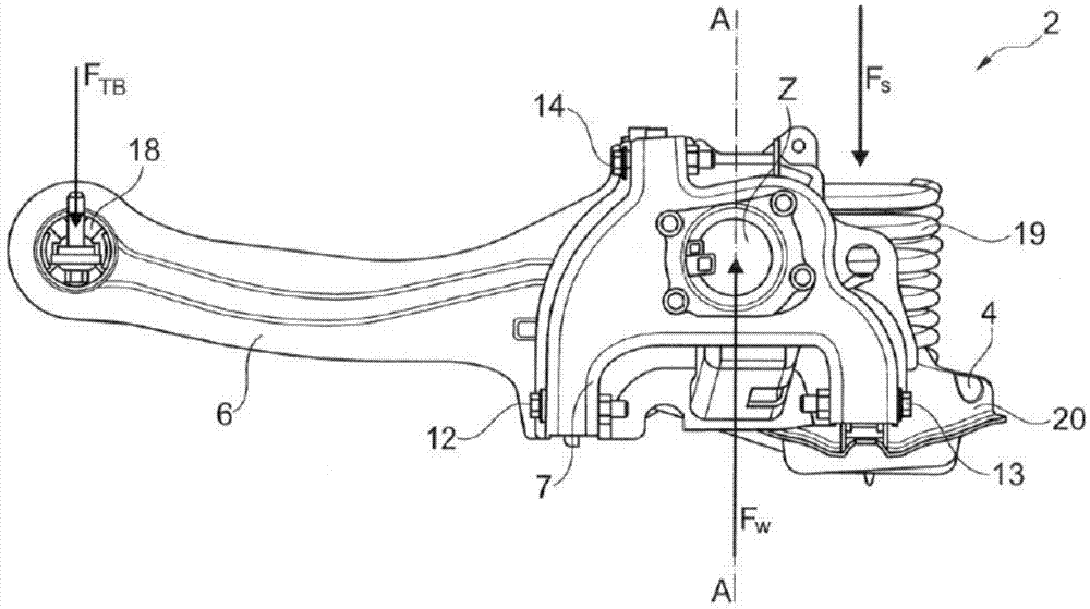
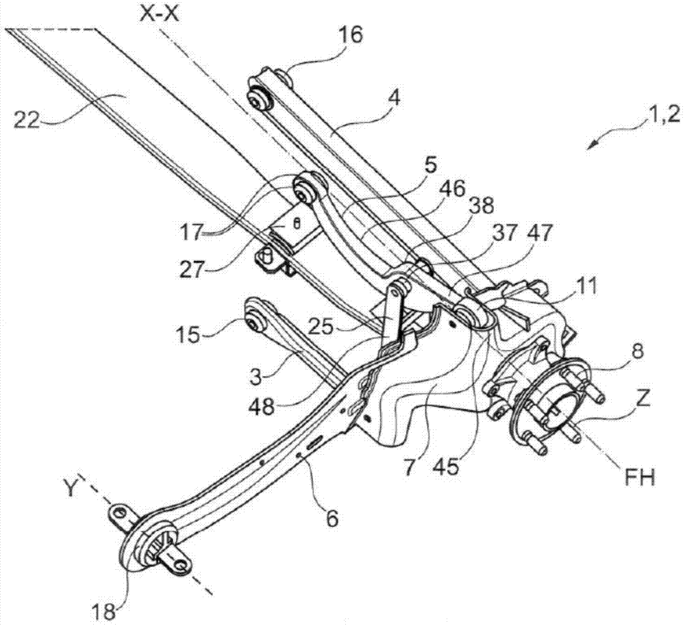
[0104] figure 1 and figure 2 The perspective views of the wheel suspension 2 ( figure 1 ) and side view ( figure 2 ). Wheel suspensions 2 according to the prior art are known as trailing arm axles.

[0105] The wheel suspension 2 is usually arranged on both sides of the vehicle, wherein the structure of the wheel suspension 2 opposite the wheel suspension 2 and not shown is exactly the same as that of the wheel suspension 2 shown, but is naturally adapted to The specific structure of the side of the wheel suspension 2.

[0106] The wheel suspension 2 has two lower control arms 3 and 4 , an upper control arm 5 and a trailing arm 6 . The control arms 3, 4 and 5 are pivotally connected to the wheel carrier 7 transversely to the longitudinal direction of the vehicle by bearing bushes 9, 10 and 11 at pivot points 12, 13 and 14, wherein only the bearing bush 11 and the Its pivot point 14 on the frame 7 can be seen. Bearing bushes 9 and 10 for lower control arms 3 and 4 (not...


PUM


Abstract

A multilink rear axle comprises a wheel carrier, a leaf spring, a first lower control arm, an upper control arm, and at least one member. The wheel carrier can rotatably support a wheel of the vehicle. The leaf spring can extend in a width direction of the vehicle that is transverse to a longitudinal direction of the vehicle. The first lower control arm can extend in the width direction and is pivotably coupled to the wheel carrier at a rear half thereof. The upper control arm can extend in the width direction and can be pivotably coupled to the wheel carrier at an attachment point that is offset from the rotation axis of the supported wheel in the longitudinal direction by less than or equal to 100 mm. The at least one member can pivotably couple the leaf spring to the upper control arm.

Description

technical field [0001] The invention relates to a multi-link rear axle for a motor vehicle. Background technique [0002] Such a multi-link rear axle with longitudinal suspension arm elements, also known as trailing arm axle, for motor vehicles is known, for example, from patent document EP 0 963 304 B1. On both sides of the vehicle, the rear axle consists of a wheel suspension with a lower control arm, an upper control arm, a transversely arranged compensating arm and a longitudinal suspension arm, also called a trailing arm and known by its Named trailing arm axle. The three control arms are arranged to extend transversely from one wheel carrier to the middle of the vehicle parallel to each other and approximately parallel to the horizontal line of the vehicle. The control arms are connected to the wheel carrier by pivot points, with the upper control arm pivoting above the wheel axis and the lower control arm and compensating arm pivoting below on either side of the whe...

Claims


Application Information

Patent Timeline
Patent Type & Authority Applications(China)
IPC IPC(8): B60G3/18B60G11/08B60G21/05
CPCB60G3/202B60G3/20B60G7/006B60G11/02B60G2200/182B60G2200/4622B60G2202/114B60G2204/121B60G2204/422B60G2204/61B60G2206/111B60G11/20B60G11/08B60G11/22B60G21/051B60G21/0551
Inventor 阿尔贝托·吉雷利·康索拉罗保罗·赞德伯尔根马克·西蒙克里斯托夫·迈耶
Owner FORD GLOBAL TECH LLC
Why Eureka
Try Eureka