Improved structure for electric vehicle control system
A technology of electric vehicle control and electric vehicle controller, applied in the direction of electric vehicles, control drives, electric power devices, etc., can solve the problems of reduced riding comfort, impact on battery life, driving mileage, large vibration, etc. The effect of weakening the feeling, improving the comfort and improving the running state
- Summary
- Abstract
- Description
- Claims
- Application Information
AI Technical Summary
Problems solved by technology
Method used
Image

Examples
Embodiment Construction
[0028] The invention provides a comprehensive utilization of the energy consumption generated during the riding process of the electric vehicle to generate electricity, and store the electric energy generated by the power generation in the auxiliary battery, which is used as a spare battery of the electric vehicle, and constitutes an electric vehicle riding Energy consumption comprehensive recycling system.
[0029] First, the electric vehicle energy recovery device composed of the electric vehicle vibration energy recovery device and the electric vehicle braking energy recovery device will be described in detail.
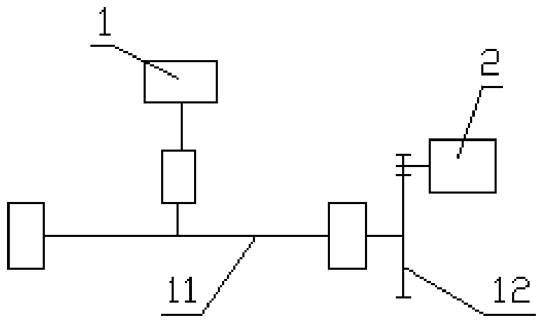
[0030] like figure 1 Shown, is electric vehicle vibration energy recovery device, comprises electric vehicle shock absorber 1, and described electric vehicle shock absorber comprises shock-absorbing fork and is located at the shock-absorbing spring on the shock-absorbing fork, is also provided with miniature generator 2, A rectifying and stabilizing circuit board ...
PUM
 Abstract
Description
Claims
Application Information
PatSnap Eureka turns technology decisions into work you can execute. Powered by our Innovation Knowledge Graph, it runs expert workflows across engineering, life sciences, materials and intellectual property. Get your review-ready output in minutes.


