
A method for adjusting the verticality of steel cages of cast-in-place piles for transmission tower foundations

A technology of transmission tower and adjustment method, which is applied in the direction of foundation structure engineering, sheet pile wall, building, etc., can solve the problems of verticality deviation of steel cage, affect the quality of pile body engineering, and no disclosed technology has been found, so as to facilitate processing and The assembly and mathematical relationship are simple and clear, and the effect of improving the quality of the project

Active Publication Date: 2016-03-16
STATE GRID CORP OF CHINA +1
View PDF5 Cites 0 Cited by
  • Summary
  • Abstract
  • Description
  • Claims
  • Application Information

AI Technical Summary

Problems solved by technology

[0002] At present, for cast-in-place piles for the foundation of transmission line iron towers, using protective layer pads to correct the verticality when lowering the steel cage will damage the hole wall, and the difficulty of lowering the steel cage is generally not used. Feeling, repeated corrections are easy to occur, and the verticality deviation of the steel cage will also affect the overall engineering quality of the pile
[0003] After searching, no disclosed technology identical to this patent application was found

Method used


Image

  • A method for adjusting the verticality of steel cages of cast-in-place piles for transmission tower foundations
  • A method for adjusting the verticality of steel cages of cast-in-place piles for transmission tower foundations

Examples


Embodiment Construction

[0023] The present invention will be further described in detail below in conjunction with the accompanying drawings and through specific embodiments. The following embodiments are only descriptive, not restrictive, and cannot limit the protection scope of the present invention.

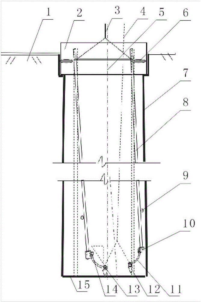
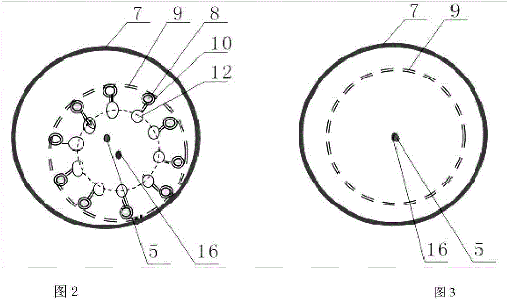
[0024] A method for adjusting the verticality of steel cages of cast-in-place piles for the foundation of power transmission towers. A borehole is formed in a ground 1 excavation well. The lower end of the borehole of the cast-in-place pile is hard soil at the bottom 15, and the side wall of the borehole of the cast-in-place pile is cylindrical. The cast-in-place pile forming hole wall 7, the upper end of the cast-in-situ pile forming hole is coaxially installed with a wellhead casing 2, and the upper end of the wellhead casing is higher than the ground;

[0025] A reinforcement cage is installed in the hole wall of the cast-in-place pile. The upper end of the reinforcement cage is connected with a sl...


PUM


Abstract

The invention relates to a perpendicularity regulating method for a foundation cast-in-place pile steel bar cage of a power transmission iron tower. According to the method, the lower rend of each vertical steel bar of the steel bar cage is respectively provided with a perpendicularity regulator, each perpendicularity regulator comprises a clamp sheet, an arc-shaped main buckle rod, a sharp head metal hammer, a heavy hammer shaft, a clamp sheet shaft and a steel wire lifting rope, one end of the arc-shaped main buckle rod is movably hinged to the clamp sheet used for clamping the vertical steel bars through the clamp sheet shaft, the other end of the arc-shaped main buckle rod is hinged to the sharp head metal hammer through the heavy hammer shaft, the lower end of the sharp head metal hammer is provided with a sharp head and can freely rotate around the heavy hammer shaft, the sharp head metal hammer and the arc-shaped main buckle rod are connected with the steel wire lifting rope, and the upper end of the steel wire lifting rope extends out of a well opening protection tube. The perpendicularity regulating method is applicable to all perpendicularity regulating work procedures of cylindrical drill holes to the bottom steel bar cage, is suitable for in-site processing, and has the advantages that the installation is simple and convenient, the repeated use can be realized, economy and practicability are realized, and more obvious effects of high speed, convenience, practicability, social benefits and economic benefits can be achieved.

Description

technical field [0001] The invention belongs to the field of cast-in-place piles for foundations of power transmission towers, in particular to a method for adjusting the verticality of steel cages of cast-in-situ piles for foundations of power transmission towers. Background technique [0002] At present, for the cast-in-place piles of the foundation of the transmission line iron tower, using the protective layer pad to correct the verticality when lowering the steel cage will damage the hole wall, and the difficulty of lowering the steel cage is generally not used. Feeling, repeated corrections are easy to occur, and the deviation of the verticality of the steel cage will also affect the overall engineering quality of the pile body. [0003] After searching, no disclosed technology identical with this patent application has been found. Contents of the invention [0004] The purpose of the present invention is to overcome the deficiencies of the prior art and provide a m...

Claims


Application Information

Patent Timeline
Patent Type & Authority Patents(China)
IPC IPC(8): E02D13/04E02D27/42
Inventor 饶友平
Owner STATE GRID CORP OF CHINA
Learn More