Backlight module and liquid crystal display

A technology of backlight module and liquid crystal panel, applied in the direction of optics, instruments, electric light source, etc., can solve the problems of increased cost and lack of versatility, and achieve the effect of facilitating installation, strong versatility, and simple structure

Active Publication Date: 2017-03-15
TCL CHINA STAR OPTOELECTRONICS TECH CO LTD
View PDF7 Cites 0 Cited by
  • Summary
  • Abstract
  • Description
  • Claims
  • Application Information

AI Technical Summary

Problems solved by technology

[0006] In this structure of the fixed bracket, when the size of the liquid crystal display needs to use a light bar with a different structure, that is, when the distance between the light sources on the light bar changes, it is necessary to redesign the distance between the light outlet holes of the fixed bracket so that it is in line with the The light source on the light bar corresponds to the lack of versatility, which increases the cost of the product

Method used


Image

  • Backlight module and liquid crystal display
  • Backlight module and liquid crystal display
  • Backlight module and liquid crystal display

Examples


Embodiment Construction

[0037] In order to better illustrate the technical features and structure of the present invention, the following will be described in detail in conjunction with the embodiments and accompanying drawings.

[0038] Figure 5 Schematic diagram of the structure of the liquid crystal display provided in this embodiment. Such as Figure 5 As shown, the liquid crystal display includes a liquid crystal panel 100 and a backlight module 200, the liquid crystal panel 100 is arranged opposite to the backlight module 200, and the backlight module 200 provides a display light source to the liquid crystal panel 100, so that all The liquid crystal panel 100 displays images.

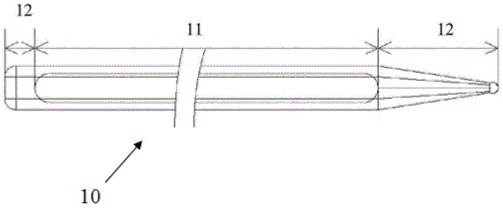
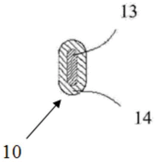
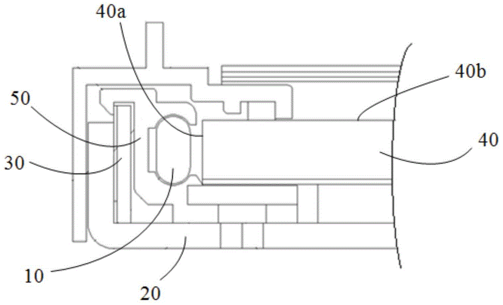
[0039] Among them, see Figure 6-9 , the backlight module 200 at least includes a backplane 20 , an edge-type light source 30 , a light guide plate 40 and a quantum strip 10 . Wherein the side-type light source 30 and the light guide plate 40 are arranged on the back plate 20, the side-type light source 30 includes ...


PUM


Abstract

Disclosed are a backlight module and a liquid crystal display containing the backlight module. The backlight module comprises: a back plate (20); a lateral-incidence type light source (30), which comprises a lamp bar (30a), wherein the lamp bar (30a) comprises a printed circuit board (301) and multiple light sources (302) mounted on the printed circuit board (301); a light guide plate (40), which is provided on the back plate (20) and is provided with a light incident face (40a) and a light emergent face (40b), wherein the light incident face (40a) directly faces the lateral-incidence type light source (30); and a quantum strip (10), wherein the quantum strip (10) is mounted between the light guide plate (40) and the lateral-incidence type light source (30) by means of a fixing bracket (50). The fixing bracket (50) is approximately a hollow cylinder. The fixing bracket (50) is provided with an accommodation space (501) used for placing the quantum strip (10), a first window (502) facing the light guide plate and a second window (503) facing the lateral-incidence type light source. The length of the second window (503) is comparable to the length of the lamp bar (30a). On the lamp bar (30a), a supporting beam (303) is provided between two adjacent light sources (302). The length of the supporting beam (303) is less than or equal to the width of the second window (503), and the height of the supporting beam (303) is not less than the height of the light sources (302). The lamp bar (30a) is assembled in the second window (503).

Description

technical field [0001] The invention relates to the technical field of liquid crystal displays, in particular to a backlight module and a liquid crystal display including the backlight module. Background technique [0002] Liquid crystal display (LCD) has the advantages of thin body, low power consumption, and no radiation, and has been widely used, such as mobile phones, digital cameras, computers, TV screens, and the like. Most of the liquid crystal displays on the market are backlight liquid crystal displays, including a liquid crystal panel and a backlight module. The liquid crystal panel and the backlight module are arranged opposite to each other. With the development of society, users have higher and higher requirements for the quality of the LCD display screen. In order to improve the color saturation of the screen, the color saturation of the screen can be improved by improving the color saturation of the light bar in the backlight module. Now Some technologies add...

Claims


Application Information

Patent Timeline
Patent Type & Authority Patents(China)
IPC IPC(8): G02F1/13357
CPCF21S8/00F21V17/00G02F1/1335
Inventor 贺虎丘永元
Owner TCL CHINA STAR OPTOELECTRONICS TECH CO LTD
Why Eureka
Try Eureka