Three-phase symmetric printed winding

A technology of printing windings and phase windings, applied in the shape/style/structure of winding conductors, electric components, manufacturing motor generators, etc., to achieve the effects of good heat dissipation, high power-to-volume ratio, and small torque ripple

Inactive Publication Date: 2014-12-17
GUANGXI NORMAL UNIV
View PDF4 Cites 2 Cited by
  • Summary
  • Abstract
  • Description
  • Claims
  • Application Information

AI Technical Summary

Problems solved by technology

Apparently the existing wound disc three-phase windings cannot meet these requirements
In order to solve the problems that cannot be solved by the prior art, the present invention provides a three-phase symmetrical printed winding to meet the above requirements

Method used


Image

  • Three-phase symmetric printed winding
  • Three-phase symmetric printed winding
  • Three-phase symmetric printed winding

Examples


Embodiment Construction

[0029] The present invention will be further described below in conjunction with the accompanying drawings and embodiments.

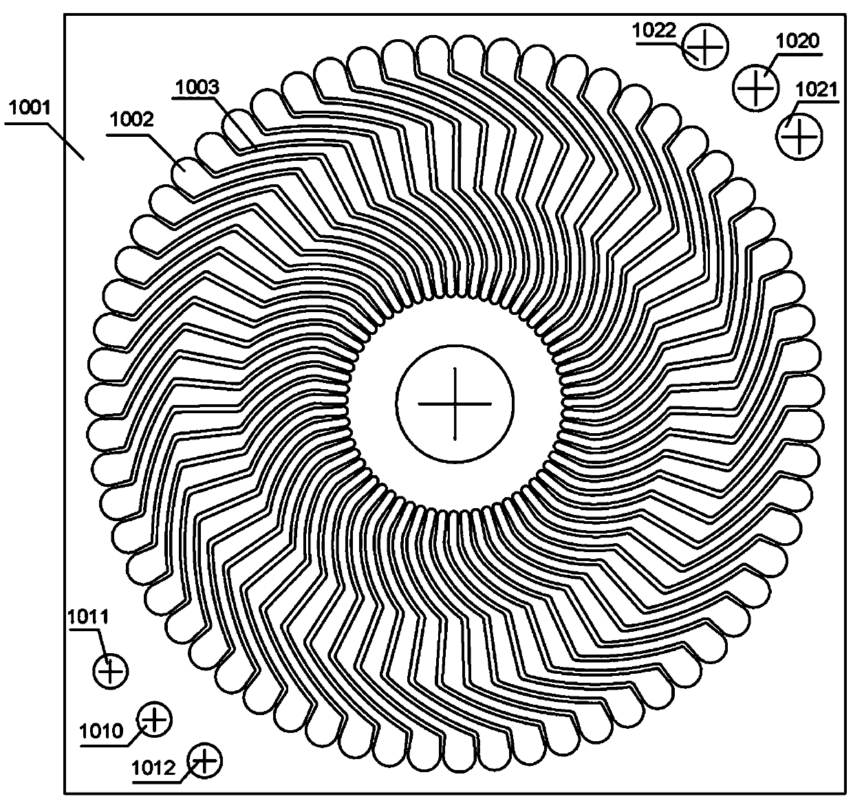
[0030] The three-phase symmetrical printed winding in this example is composed of 4 (M=1 in 4M) conductor sheets containing 63 (N=21 in 3N) conductors overlapped.

[0031] In order to describe the product in detail and accurately, this example explains from the perspective of product production.

[0032] 1. Making punching film: such as figure 1 As shown, on a uniform copper alloy sheet with a thickness of 0.3 mm, a stamping sheet 1001 is produced by using a die or chemical etching. There are 3N punching grooves 1002 evenly distributed on the punching sheet 1001, and these punching grooves 1002 are evenly distributed around the axis and have the same shape. Three small-diameter positioning holes 1010, 1011 and 1012 are located in the lower left corner, and three large-diameter positioning holes 1020, 1021 and 1022 are located in the upper right co...


PUM

PropertyMeasurementUnit
Thicknessaaaaaaaaaa

Abstract

The invention discloses a three-phase symmetric printed winding which is applied to high-precision servo driving motors with high dynamic performance and comprises 4M conductor sheets. The 4M (the M is a positive integer) conductor sheets are overlapped on one another to form the three-phase symmetric printed winding, each conductor sheet comprises 3N (the N is a positive integer larger than or equal to 4) conductors, the various sheets are adhered with one another by insulating grey cloth, a group comprises two adjacent sheets, and the outer ends of the conductors of the two conductor sheets in each group are uniformly staggered from one another in a crossed manner; the inner ends, which are aligned with one another pairwise, of the conductors of the two conductor sheets in each group are communicated with one another, and the outer ends, which are aligned with one another pairwise, of the conductors of the conductor sheets in each two corresponding groups are communicated with one another; six distributed windings can be acquired according to laws of three-phase windings with 60-degree phase belts after the six conductors on the uppermost layer and the six conductors on the lowermost layer are disconnected from one another, and are denoted as U+, U-, V+, V-, W+ and W- respectively, the distributed winding U+ and the distributed winding U- are connected with each other in series to obtain a U-phase winding, the distributed winding V+ and the distributed winding V- are connected with each other in series to obtain a V-phase winding, the distributed winding W+ and the distributed winding W- are connected with each other in series to obtain a W-phase winding, and the tail ends of the U-phase winding, the V-phase winding and the W-phase winding are connected with one another.

Description

technical field [0001] The invention relates to a three-phase permanent magnet synchronous motor, in particular to a three-phase symmetrical printed winding of the three-phase permanent magnet synchronous motor. Background technique [0002] At present, due to congenital defects such as positioning torque and air gap magnetic density distortion of the known three-phase permanent magnet synchronous motor with teeth and slots, the torque of the motor will fluctuate, vibration and noise will occur, and the speed will fluctuate, so that the motor cannot run smoothly and affect motor performance. At the same time, it causes the motor to generate undesired vibration and noise. In variable speed drives, when the torque ripple frequency coincides with the mechanical resonance frequency of the stator or rotor, the vibration and noise generated by the detent torque will be amplified. The existence of detent torque also affects the low-speed performance of the motor in the speed cont...

Claims


Application Information

Patent Timeline
IPC IPC(8): H02K3/26H02K3/28H02K15/04
Inventor 黄植功
Owner GUANGXI NORMAL UNIV
Why Eureka
Try Eureka