Drive device, electronic component carrying device, electronic component inspection device
A drive device, technology of electronic components, applied in the field of robotics
- Summary
- Abstract
- Description
- Claims
- Application Information
AI Technical Summary
Problems solved by technology
Method used
Image
Examples
no. 1 Embodiment approach
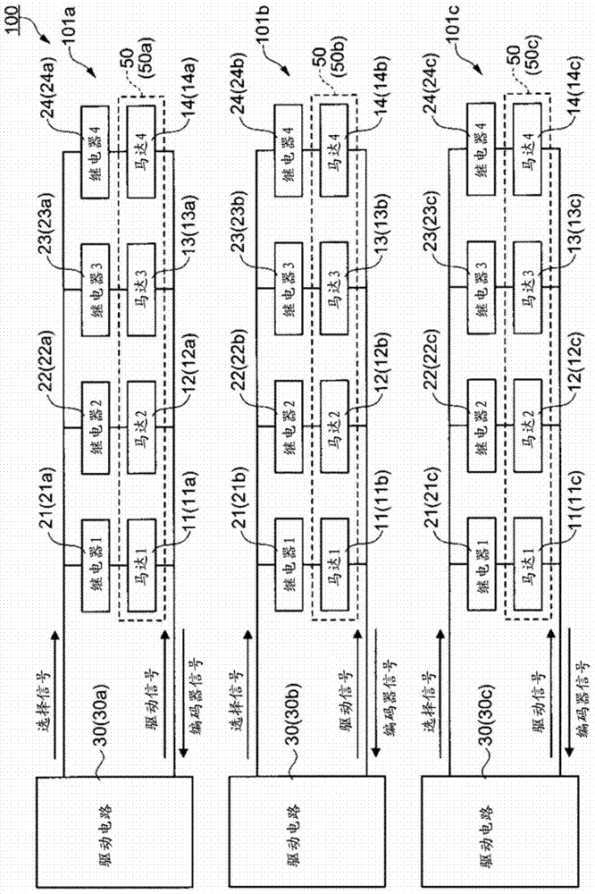
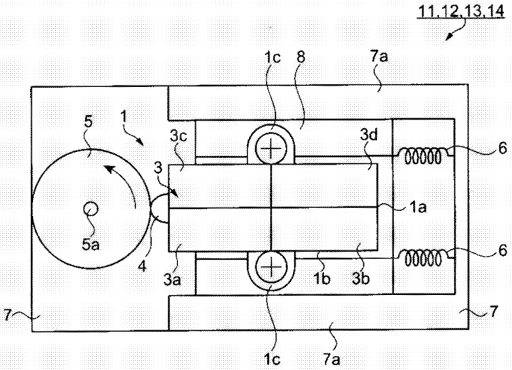
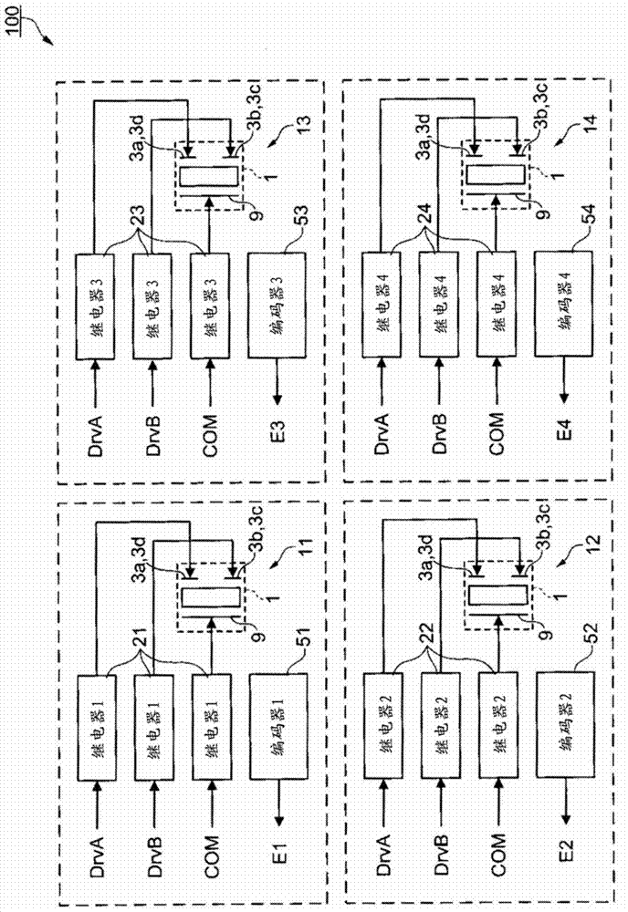
[0082] figure 1 It is a schematic block diagram showing the configuration of the drive device according to the first embodiment. figure 2 It is a schematic diagram showing the configuration of the piezoelectric motor used in the driving device according to the first embodiment. image 3 It is a block diagram showing the configuration of the drive device according to the first embodiment. Figure 4 It is a block diagram showing the configuration of the drive circuit according to the first embodiment. Figure 5 It is a figure explaining the drive control method of the drive device concerning 1st Embodiment.
[0083] drive unit
[0084] First, the schematic configuration of the drive device according to the first embodiment will be described. figure 1 It is a schematic block diagram showing the configuration of the drive device according to the first embodiment. Such as figure 1 As shown, the drive device 100 according to the first embodiment is composed of three drive uni...
no. 2 Embodiment approach
[0137] drive unit
[0138] Next, the driving device according to the second embodiment will be described. The driving device according to the second embodiment differs from the first embodiment in that the vibration body of the piezoelectric motor is excited not only in the bending vibration but also in the longitudinal vibration, but the other configurations are almost the same. Hereinafter, this embodiment will be described focusing on differences from the above-described embodiments, and descriptions of the same items will be omitted.
[0139] Figure 6 It is a schematic diagram showing the configuration of a piezoelectric motor used in the drive device according to the second embodiment. Figure 7 It is a block diagram showing the configuration of the driving device according to the second embodiment. Figure 8 It is a block diagram showing the configuration of the drive circuit according to the second embodiment.
[0140] The drive device 102 according to the second e...
no. 3 Embodiment approach
[0148] Electronic component conveying equipment and electronic component inspection equipment>
[0149] Next, an electronic component conveyance device and an electronic component inspection device according to a third embodiment will be described. The electronic component conveying device and the electronic component inspection device according to the third embodiment include a positioning mechanism having the same basic configuration as that of the driving device according to the first embodiment. Hereinafter, this embodiment will be described focusing on differences from the above-described embodiments, and descriptions of the same matters will be omitted.
[0150] First, an example of electronic components transported or inspected by the electronic component transport device and the electronic component inspection device according to the third embodiment will be described. Figure 9 It is a figure which shows an example of the electronic component which concerns on 3rd Em...
PUM
 Abstract
Description
Claims
Application Information
 - R&D
- Intellectual Property
- Life Sciences
- Materials
- Tech Scout
- Unparalleled Data Quality
- Higher Quality Content
- 60% Fewer Hallucinations
Browse by: Latest US Patents, China's latest patents, Technical Efficacy Thesaurus, Application Domain, Technology Topic, Popular Technical Reports.
© 2025 PatSnap. All rights reserved.Legal|Privacy policy|Modern Slavery Act Transparency Statement|Sitemap|About US| Contact US: help@patsnap.com


