Touch internal full-closed-loop control LED dimming drive circuit

A technology of dimming drive and touch control, which is applied in the direction of lamp circuit layout, light source, electric light source, etc. It can solve the problems of input voltage fluctuation, mass production inductance value deviation, and general effect, so as to improve circuit reliability and reduce faults The effect of risk and reliability improvement

Active Publication Date: 2014-12-17
闵长伟
View PDF3 Cites 3 Cited by
  • Summary
  • Abstract
  • Description
  • Claims
  • Application Information

AI Technical Summary

Problems solved by technology

(Figure 2) This is a simple and effective control strategy, but since this is an open-loop control mode, it can only detect the peak current on the inductor, but cannot detect the output current. The output current accuracy is prone to deviations in three situations: 1. Input voltage fluctuations
(Open-loop control, unable to feedback, caused by system delay); 2. Deviation of inductance value in ma

Method used


Image

  • Touch internal full-closed-loop control LED dimming drive circuit
  • Touch internal full-closed-loop control LED dimming drive circuit
  • Touch internal full-closed-loop control LED dimming drive circuit

Examples


Example Embodiment

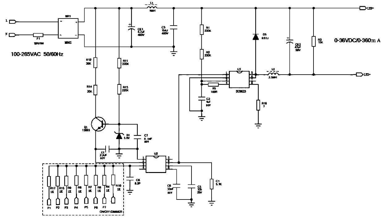
[0029] The external programmable PWM signal input provided by the chip DU8623 used in the present invention controls the output of the chip PWM signal via the MCU, and sets the output duty ratio of the PWM signal;

[0030] in figure 1 In, when the touch point is touched by hand (ON / OFF-DIMMER point or other contact points on the circuit, 1-8 touch points can be connected), the clutter signal induced by the human body enters the MUC chip through the resistance, which activates The data storage circuit inside the MCU chip, the data storage circuit will then program the programmed LED light source output current duty cycle data, and send the data to the main control calculation circuit, and then use the above data to establish an internal database, through the database Convert the signal into the actual output duty cycle signal of the LED, and send the corresponding control signal to the DU8623 DIM dimming pin according to the set data, so that the LED can adjust its luminous flux o...


PUM


Abstract

The invention relates to a touch internal full-closed-loop control LED dimming drive circuit and aims to provide a novel full-closed-loop control strategy to fully avoid deviations and substantially realize true LED constant current. The touch internal full-closed-loop control LED dimming drive circuit comprises a data storage circuit, an input circuit, a master control computing circuit and a self-calibration circuit. The touch internal full-closed-loop control LED dimming drive circuit has the function of opening and short circuit protection for an Rcs sampling resistor. The touch internal full-closed-loop control LED dimming drive circuit is applicable to LED drive power sources.

Description

technical field [0001] The invention relates to an LED driving circuit, more specifically, to a touch-type built-in wide voltage input LED dimming driving circuit. Background technique [0002] According to the load characteristics of LED desk lamps, there are not many schemes using wide voltage 100-265V built-in touch dimming drivers, and the topology structure of using non-isolated constant current driving power is basically a BUCK step-down structure, which will use non-isolated The development of LED constant current control technology is divided into three generations, discuss the development of the principle of control strategy to achieve constant current, analyze the advantages and disadvantages of each generation, and what breakthroughs each generation has. Based on the DU8623 chip, introduce the latest generation of integrated closed-loop current control technology, and introduce in detail how this control strategy makes breakthroughs in improving the accura...

Claims


Application Information

Patent Timeline
IPC IPC(8): H05B37/02
Inventor 闵长伟
Owner 闵长伟
Why Eureka
Try Eureka