Supercharge Your Innovation With Domain-Expert AI Agents!

pressure vessel

A technology for pressure vessels and containers, applied in the field of pressure vessels, can solve problems such as limited service life

Active Publication Date: 2017-06-23
MIKROWELLEN SYST MWS
View PDF1 Cites 0 Cited by
  • Summary
  • Abstract
  • Description
  • Claims
  • Application Information

AI Technical Summary

Problems solved by technology

The cooling in this region of the pressure vessel and the relatively high heating in other regions of the pressure vessel lead on the one hand to high stresses in the material of the pressure vessel; Limited service life due to heavy loads due to significant thermal and thermal changes each time the sample passes

Method used


Image

  • pressure vessel
  • pressure vessel
  • pressure vessel

Examples


Embodiment Construction

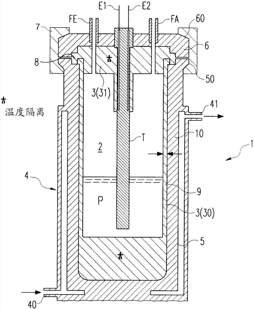
[0052] figure 1 and figure 2 A first and a second embodiment of a pressure vessel 1 (hereinafter also referred to as vessel or sample vessel) according to the invention are shown for containing a sample P to be heated in order to initiate and / or facilitate a chemical pressure reaction on the sample P and / or physical stress response. The pressure vessel 1 consists of a high-pressure resistant material, for example a metal, preferably steel, particularly preferably a special metal alloy. The pressure vessel 1 is here preferably designed such that it can be used at pressures of up to at least 200 bar, preferably up to at least 500 bar, and at temperatures above 300° C.

[0053]The pressure vessel 1 surrounds the reaction chamber 2 . The sample P is arranged in the reaction chamber 2 for sample processing and can be withdrawn therefrom preferably through the opening.

[0054] Furthermore, the pressure vessel 1 has an insulating lining 3 (the so-called liner) surrounding the ...


PUM


Abstract

The invention describes a pressure vessel for containing a sample to be heated, wherein the pressure vessel has a bottom (5, 104) and a cover (6, 105), which can be closed to each other and in the closed state Fully enclosing a reaction chamber for initiating and / or facilitating a chemical pressure reaction and / or a physical pressure reaction, wherein the bottom (5, 104) and the cover (6, 105) can be placed in an open access position and a closed microwave The processing positions are automatically moved relative to each other, wherein the sample holder ( 101 ) and / or the container liner ( 9 ) is interconnected with the cover ( 6 , 105 ).

Description

technical field [0001] The invention relates to a pressure vessel, a system comprising a housing structure with one or more such pressure vessels, and a method for initiating and / or promoting a chemical pressure reaction and / or a physical pressure reaction on a sample by means of a pressure vessel. Background technique [0002] A device for initiating and / or promoting chemical and / or physical pressure reactions on a sample by applying microwaves is known from DE4114525. The device shown in this document has cooling means in the region of its upper side, ie above the region in which the sample is accommodated in the sample container, so that corresponding gaseous products occurring in the reaction chamber can condense and be fed back to the reaction. In order to securely close the coupling opening, it is desirable to have a relatively high temperature in the region of the sample container surrounding the sample itself, so that this region can expand accordingly in order to be...

Claims


Application Information

Patent Timeline
Patent Type & Authority Patents(China)
IPC IPC(8): B01J3/04
CPCB01J2219/1215B01J2219/1218B01J2219/123B01J2219/1233B01J2219/1236B01J2219/1242B01J3/03B01J3/048H05B6/806B01J19/126
Inventor 沃纳·劳藤施拉格尔
Owner MIKROWELLEN SYST MWS
Features
  • R&D
  • Intellectual Property
  • Life Sciences
  • Materials
  • Tech Scout
  • Unparalleled Data Quality
  • Higher Quality Content
  • 60% Fewer Hallucinations
Learn More