Milling method of diffuser

A diffuser and milling technology, applied in milling machine equipment, milling machine equipment details, metal processing equipment, etc., can solve problems such as low processing efficiency and poor product quality, and achieve reduced tool cost, shortened processing time, and improved profile quality. Effect

Inactive Publication Date: 2014-12-24
CHONGQING JIANGJIN SHIPBUILDING IND
View PDF8 Cites 8 Cited by
  • Summary
  • Abstract
  • Description
  • Claims
  • Application Information

AI Technical Summary

Problems solved by technology

[0006] Aiming at the technical problems of poor product quality and low processing efficiency in the prior art, the present invention provides a diffuser milling method. By optimizing the milling path, the layered rough milling inlet has no Blade section, outlet without blade section, and then mill the blade body margin at one time, which reduces the number of milling layers and tool idle travel, and improves the milling efficiency; at the same time, rough milling the blade in advance, and then milling the blade body remaining The amount reduces the strain force of the blade, avoids the generation of knife marks, and improves the surface quality of the blade

Method used


Image

  • Milling method of diffuser
  • Milling method of diffuser
  • Milling method of diffuser

Examples


Embodiment Construction

[0022] The specific implementation manner of the present invention will be described in further detail below in conjunction with the accompanying drawings.

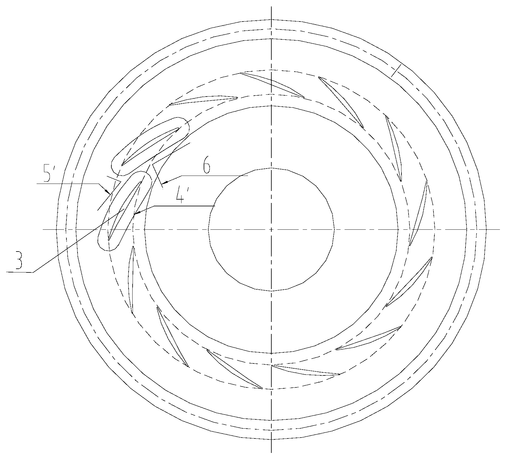
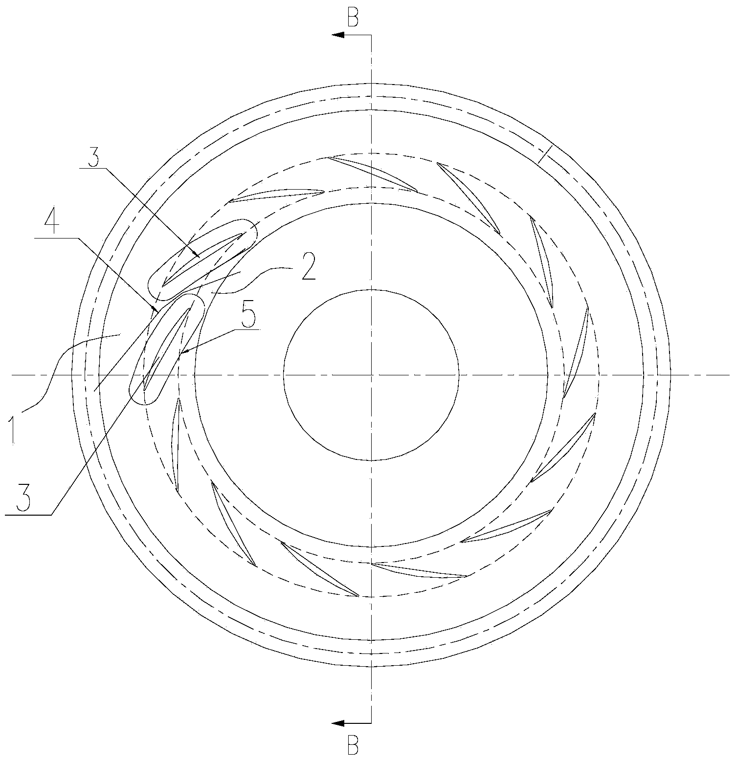
[0023] Such as figure 2 Shown, diffuser milling method of the present invention, comprises the following steps:

[0024] a. The path from the outlet bladeless section 1 to the inlet bladeless section 2 between two adjacent blades 3 is used as the first milling path 4, and the first milling path 4 is layered and rough milled, and all adjacent two blades are sequentially milled. The milling of the outlet bladeless section 1 to the inlet bladeless section 2 between the blades 3 is completed;

[0025] b. The path around the blade 3 is used as the second milling path 5 , and the margin of the blade body of the blade 3 is milled at one time according to the second milling path 5 , and all the blades 3 are milled in turn.

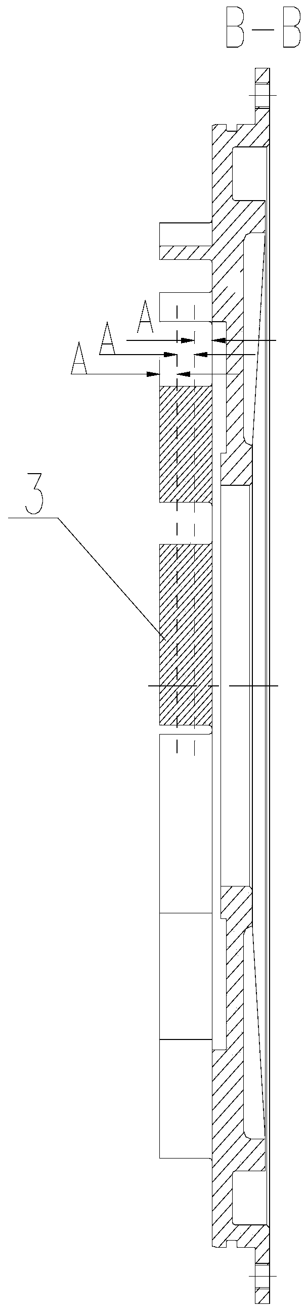
[0026] Such as image 3 As shown, in step a, the first milling path 4 is milled in three layers, and t...


PUM


Abstract

The invention relates to a milling method of a diffuser. The milling method comprises the following steps: a. with a route from an outlet blade-less section to an inlet blade-less section between two adjacent blades as a first milling route, roughly milling the blades in a layering manner according to the first milling route, and sequentially milling the outlet blade-less sections and the inlet blade-less sections between every two adjacent blades; and b. with a route at the periphery of the blades as a second milling route, milling the margins of the blades in one step according to the second milling route, thus sequentially milling all the blades. By adopting the milling method, the milling quality and milling efficiency of the diffuser can be improved.

Description

technical field [0001] The invention relates to the technical field of mechanical processing, in particular to a method for milling a diffuser. Background technique [0002] In recent years, with the shortage of energy and the general increase of processing costs, it is imperative for all enterprises to transform into environmentally friendly and energy-saving enterprises. Among them, the improvement of production efficiency is the most effective means for companies to save energy and reduce production costs. As a key component in the power booster system, the diffuser has a large milling allowance, and the milling method directly affects the processing efficiency and quality of the diffuser, which is related to the cost of the enterprise and the performance of the power system. [0003] Such as figure 1 As shown, the existing diffuser milling method is layered milling, in which the milling depth Ap is within the cutting depth range allowed by the tool, and the specific val...

Claims


Application Information

Patent Timeline
Patent Type & Authority Applications(China)
IPC IPC(8): B23C3/00
Inventor 鲁建于曾凌云谭伟
Owner CHONGQING JIANGJIN SHIPBUILDING IND
Why Eureka
Try Eureka