

Polisher, polishing head quick-detaching mechanism and using method thereof
A technology of grinding heads and grinders, which is applied to the parts of grinding machine tools, grinding/polishing equipment, metal processing equipment, etc., can solve the problems such as difficult replacement of grinding heads, and achieve the advantages of small man-hour consumption, fast installation and disassembly, and easy operation simple effect
- Summary
- Abstract
- Description
- Claims
- Application Information
AI Technical Summary
Problems solved by technology
Method used
Image

Examples
Embodiment 1
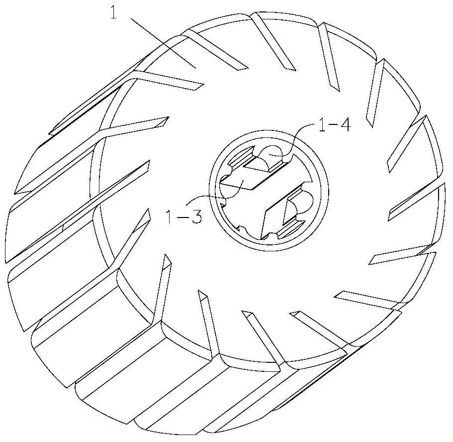
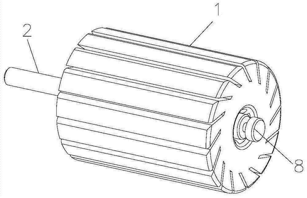
[0049] In this embodiment, the elastic member adopts the shrapnel 4, such as Figure 4 Figure 8 As shown, the shrapnel 4 includes a rear section 4-1, an arched section 4-2 and a front section 4-3, and the rear section 4-1, the arched section 4-2 and the front section 4-3 are sequentially connected to form the main part of the shrapnel 4, The connection point of rear section 4-1 and arch section 4-2 forms a horizontal connection with the connection point of front section 4-3 and arch section 4-2, and the midline of the highest point of arch section 4-2 is different from the horizontal connection line. Coincidentally, in this embodiment, preferably, the highest point of the elastic sheet 4 is biased outward.
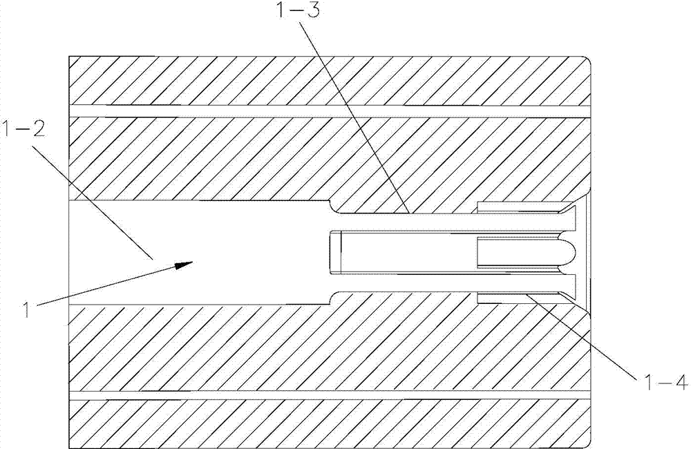
[0050] Such as Figure 6 , the front end of the output shaft 2 is hollow, the output shaft 2 has a through hole 3-1 communicating with the hollow part of the output shaft 2, the main part of the shrapnel 4 is placed in the hollow part of the output shaft 2, and the arch...
Embodiment 2
[0058] Such as Figure 9 , the elastic member in embodiment 2 adopts steel wire 5, and steel wire 5 has the characteristics of fast forming, and the structure of steel wire 5 is basically the same as that of shrapnel 4. After changing from shrapnel 4 to steel wire 5, its corresponding push rod 6 also has some changes. There are 4 limiting grooves 3 in the example, wherein there are through holes 3-1 on the two opposing limiting grooves 3, and there are two arched sections 4-2 of the steel wire 5, and the two arched sections 4-2 are connected to each other. Symmetrical, the two arched sections 4-2 protrude from the corresponding through holes 3-1 respectively, the push rod 6 has a tail part 6-7, and the tail part 6-7 is connected with the first journal 6-1, as Figure 10 , A notch 6-8 is provided on the tail part 6-7, and the rear section of the steel wire 5 is embedded in the notch 6-8, so that the rear section of the steel wire 5 is hooped on the end face of the first journal...
Embodiment 3
[0061] The difference between Embodiment 3 and Embodiment 1 lies in the unlocking mechanism. The unlocking mechanism of Embodiment 1 is to press the push rod 6 to cause radial deformation of the elastic member. This embodiment starts from another method (not shown) , using the method of rotating the push rod 6, the push rod is equipped with a cam, and the travel curve of the cam is used to make the shrapnel 4 open regularly or return to the normal state. When the shrapnel 4 is opened, the grinding head 1 cannot be removed , when the shrapnel 4 is in a non-expanded normal state, the grinding head can be quickly removed. In this way, the unlocking mechanism can also control the elastic member.
PUM
 Abstract
Description
Claims
Application Information