Dual-head 3D printer capable of rotatably switching printing heads

A 3D printer and print head technology, applied in the field of 3D printers, can solve problems such as damage to the surface, printing can not continue, affect the surface quality of the workpiece, etc., to achieve the effect of solving poor printing quality

Active Publication Date: 2014-12-24
苏州江南嘉捷光机电技术有限公司
View PDF7 Cites 35 Cited by
  • Summary
  • Abstract
  • Description
  • Claims
  • Application Information

AI Technical Summary

Problems solved by technology

First of all, due to the same height of the two wire outlets during the printing process, they will contact and collide with the formed surface respectively. Although the accuracy is not greatly affected, it will destroy the generated surface. In severe cases, the unfinished parts will be damaged. knocked down, so that printing cannot continue
Secondly, under the effect of high temperature on the non-working wire outlet during printing, a small amount of printing material will accumulate at the wire outlet, and it will also be coated on the formed surface during the printing process, which seriously affects the surface quality of the workpiece.

Method used


Image

  • Dual-head 3D printer capable of rotatably switching printing heads
  • Dual-head 3D printer capable of rotatably switching printing heads
  • Dual-head 3D printer capable of rotatably switching printing heads

Examples


Embodiment 1

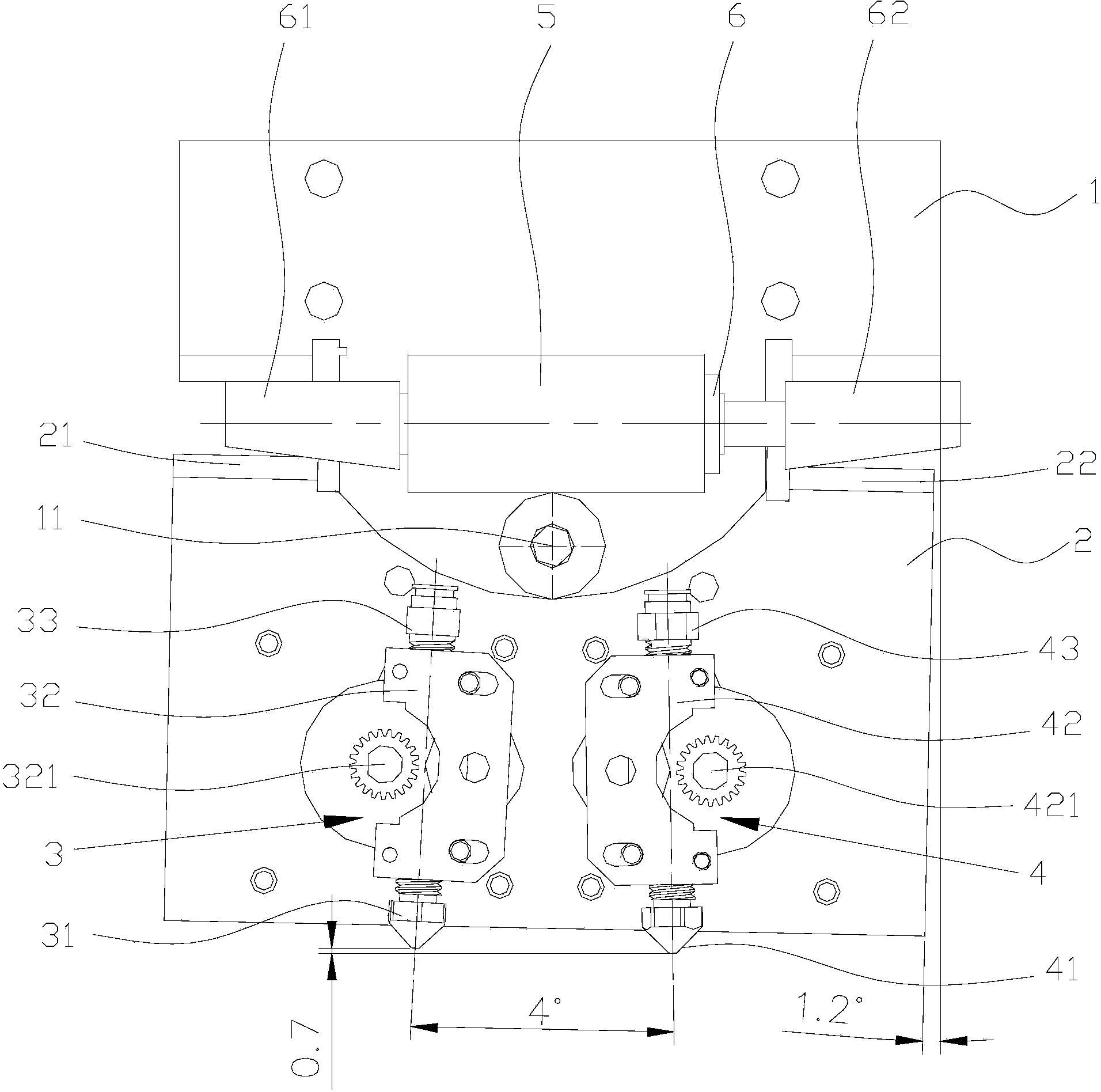
[0026] see figure 1 , a dual-head 3D printer that can rotate and switch print heads, it includes a fixed plate 1, a mounting plate 2 rotatably connected to the fixed plate 1, a first print head 3 and a second print head mounted on the mounting plate 2 in parallel print head 4.

[0027] A fixed rotating shaft 11 is arranged on the fixed plate 1 , and the axial direction of the fixed rotating shaft 11 in this embodiment is arranged along the horizontal direction. The mounting plate 2 is rotatably connected to the fixed rotating shaft 11 with the axis of the fixed rotating shaft 11 as the center line of rotation. The first printing head 3 is located on the lower left side of the fixed rotating shaft 11 , and the second printing head 4 is located on the lower right side of the fixed rotating shaft 11 . The first print head 3 and the second print head 4 are arranged left and right symmetrically with the vertical line where the axis of the fixed rotating shaft 11 is located as the...

Embodiment 2

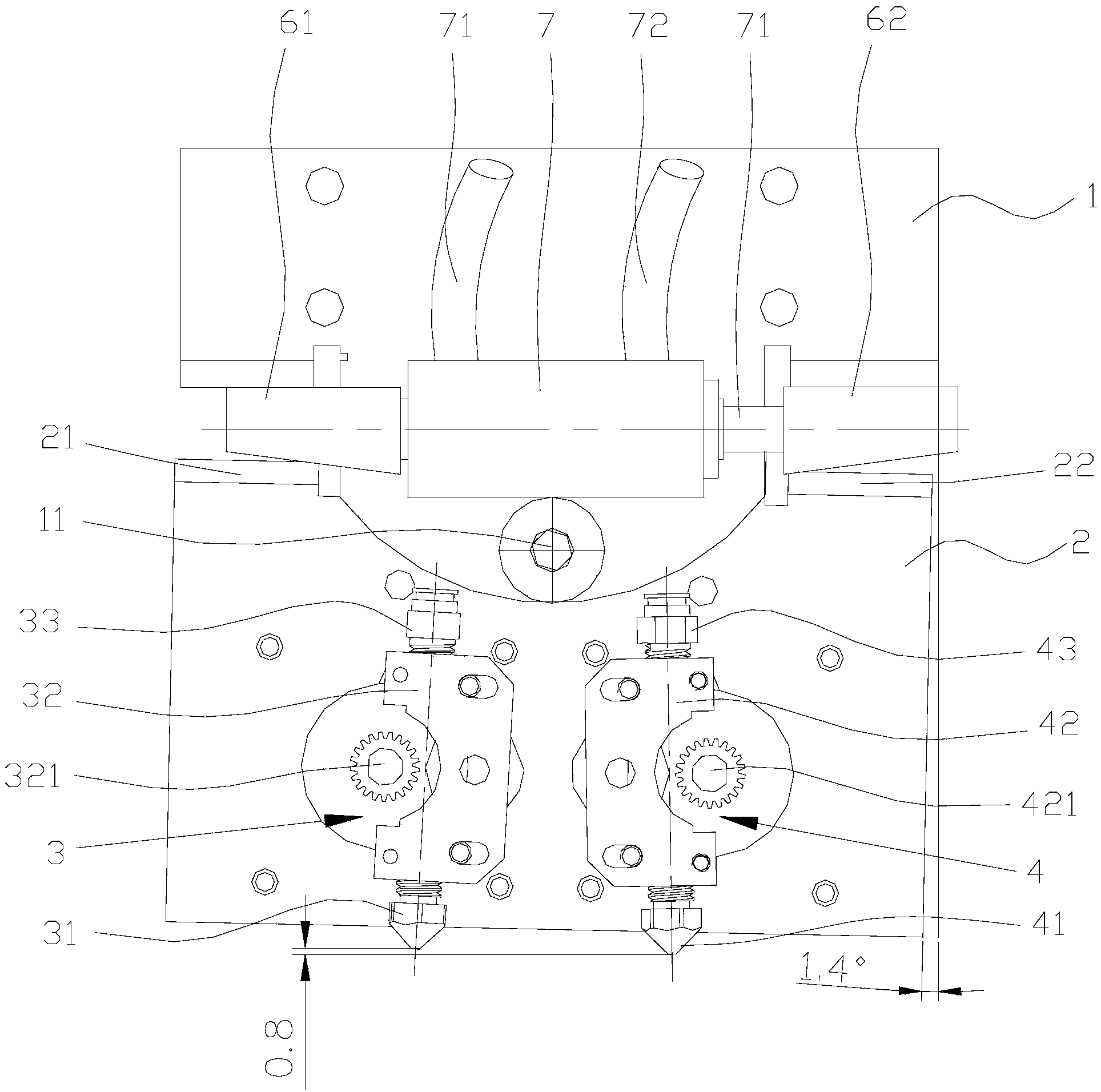
[0046] Such as figure 2 As shown, the basic structure of this embodiment is the same as that of Embodiment 1, the difference is that the electromagnetic coil 5 is replaced by a double-acting cylinder 7, and the double-acting cylinder 7 is arranged horizontally, and a piston rod that can move left and right along its own axis is arranged inside it. 71. Left wedge block 61 is installed on the left end of piston rod 71, and right wedge block is installed on the right end of piston rod 71. The left and right sides of the double-acting cylinder 7 are respectively provided with a first air pipe 72 and a second air pipe 73, and the air source of the external air supply device supplies air to the first air pipe 72 and the second air pipe 73 respectively. Down, push the piston rod 71 to move left and right, so as to drive the mounting plate 2 to rotate counterclockwise or clockwise, so as to achieve the technical effect of swinging left and right to switch the print head for printing...

Embodiment 3

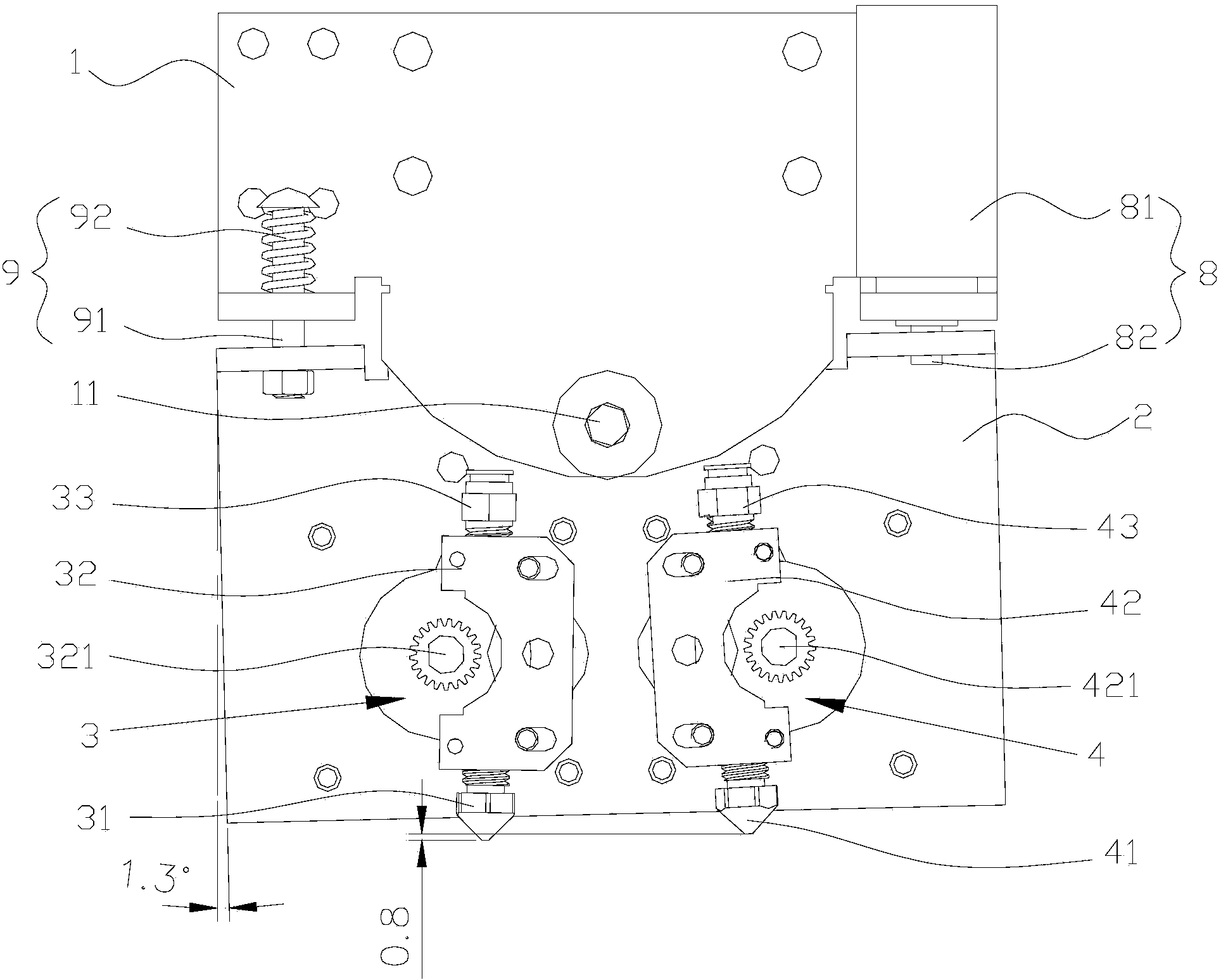
[0050] Such as image 3 As shown, the difference between this embodiment and Embodiment 1 is that the driving mechanism includes a reversing electromagnetic device 8 installed on the right side of the fixed plate 1, and the reversing electromagnetic device 8 includes a reversing electromagnetic coil 81 and is arranged on a reversing electromagnetic coil that can move up and down. To the electromagnet core 82 in the electromagnetic coil 81 , the right upper end of the electromagnet core 82 is connected to the mounting plate 2 . The driving mechanism also includes an elastic reset device 9 installed on the left side of the mounting plate 2. The elastic reset device 9 includes a stop rod 91 with one end fixed on the install plate 2. The upper end of the stop rod 91 and the fixed plate 1 A spring 92 is provided in the sleeve.

[0051] When the print head is switched to print, the reversing electromagnetic coil 81 is powered on, and the electromagnetic core 82 moves upward, drivin...


PUM


Abstract

The invention discloses a dual-head 3D printer capable of rotatably switching printing heads. The dual-head 3D printer is characterized by comprising a fixing plate, an installation plate which is arranged on the fixing plate, a first printing head and a second printing head, wherein the first printing head and the second printing head are installed on the installation plate in parallel; the fixing plate is provided with a fixed rotating shaft, and the installation plate is connected to the fixed rotating shaft in a way of rotating around the axis of the fixed rotating shaft; the first printing head is arranged below the fixed rotating shaft to the left side, and the second printing head is arranged below the fixed rotating shaft to the right side; and the dual-head 3D printer also comprises a drive mechanism for driving the installation plate to rotate along the fixed rotating shaft. The installation plate is driven by the drive mechanism to rotate, so that the structure that the heights of the two printing heads can be adjusted up and down relatively in the vertical direction, the working printing head is always maintained at a relatively low position, and the non-working printing head is maintained at a relatively high position; thus, the non-working printing head does not influence the surface of a molded workpiece, and the printing quality is improved.

Description

technical field [0001] The invention relates to a 3D printer based on FDM fusion deposition technology, in particular to a double-head 3D printer capable of rotating and switching printing heads. Background technique [0002] FDM fused deposition 3D printing technology is currently the most widely used technology. Many consumer-grade 3D printers use this printing process. It is relatively easy to implement and the cost is low. FDM fusion deposition is that the heating head heats the hot-melt material (such as ABS, PLA, nylon, wax, etc.) to a critical state, making it appear in a semi-fluid state, and then the heating head moves along the two-dimensional geometric trajectory determined by CAD under software control At the same time, the nozzle extrudes the material in a semi-fluid state, and the material solidifies instantly and rapidly to form a thin layer with a contour shape. [0003] For complex hollow parts and parts with long cantilever, the parts need to be supported ...

Claims


Application Information

Patent Timeline
Patent Type & Authority Applications(China)
IPC IPC(8): B29C67/00
Inventor 王锐刚戴宪光余华陆荣生
Owner 苏州江南嘉捷光机电技术有限公司
Why Eureka
Try Eureka