Split differential tail wing control mechanism of flapping-wing micro air vehicle

A flapping-wing aircraft and control mechanism technology, applied in the field of highly efficient miniature flapping-wing aircraft tail control mechanism, can solve the problems of weak maneuverability and agility, and achieve the effect of simple structure and strong reliability

Active Publication Date: 2014-12-24
北京北航天宇长鹰无人机科技有限公司
View PDF6 Cites 19 Cited by
  • Summary
  • Abstract
  • Description
  • Claims
  • Application Information

AI Technical Summary

Problems solved by technology

[0006] The purpose of the present invention is to solve the current situation of weak maneuverability and agility of the existing miniature flapping-wing aircraft, improve the operating efficiency of the miniature flapping-wing aircraft, and improve the flight performance. split differential tail control mechanism for micro flapping wing aircraft

Method used


Image

  • Split differential tail wing control mechanism of flapping-wing micro air vehicle
  • Split differential tail wing control mechanism of flapping-wing micro air vehicle
  • Split differential tail wing control mechanism of flapping-wing micro air vehicle

Examples


Embodiment Construction

[0024] The present invention will be further described in detail with reference to the accompanying drawings and embodiments.

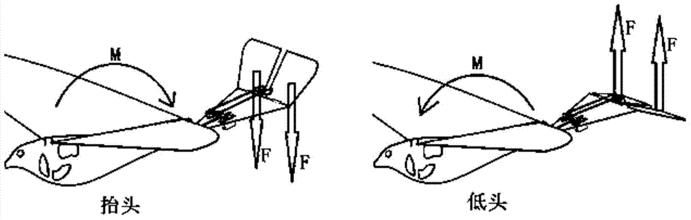
[0025] Generally speaking, the roll of the aircraft is achieved by greatly changing the lift difference between the left and right of the body; for the micro-flapping wing aircraft, since the flapping wing is a moving part, it is necessary to install or modify a mechanism that greatly changes the lift difference on it. Difficult; and the comparatively large empennage can be regarded as a static part except the direction of torsion. As long as the original single-piece tail is divided into two pieces, and a large differential push-pulls to different angles, it can bring a strong rolling moment to the aircraft; yaw moment.

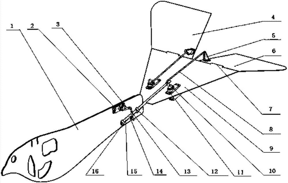
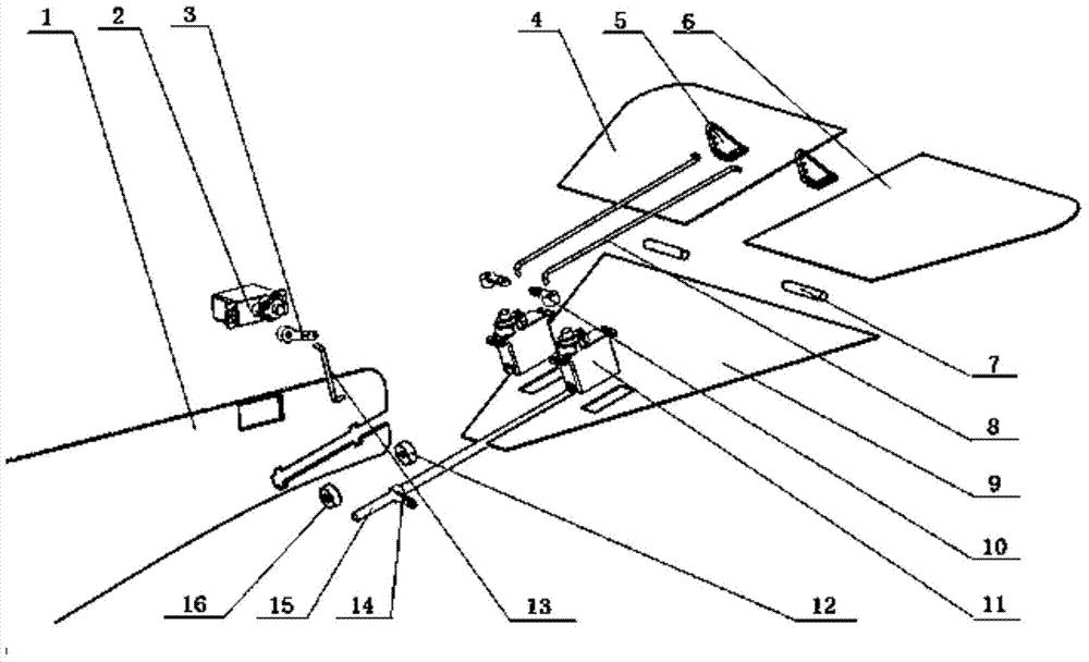
[0026] According to the above-mentioned principle, the present invention is a split type differential tail control mechanism of a miniature flapping wing aircraft, such as figure 1 , figure 2 As shown, it includes body frame 1, ...


PUM


Abstract

The invention discloses a split differential tail wing control mechanism of a flapping-wing micro air vehicle. The control mechanism is characterized in that a torsional steering engine is mounted on a machine body frame and connected to one end of a torsional steering engine rocking arm; a torsional connection rod is connected to the other end of the torsional steering engine rocking arm; a torsional shaft rocking arm is connected to the other end of the torsional connecting rod and connected with a torsional shaft; a front bearing and a rear bearing are mounted on the machine body frame; the torsional shaft is fixedly connected to a tail vane mounting surface; the tail vane mounting surface is connected with a left tail vane and a right tail vane through two tail vane hinges respectively; a left tail vane machine and a right tail vane machine are mounted on the tail vane mounting surface; a left tail vane rocking arm is arranged on the left tail vane; a right tail vane rocking arm is arranged on the right tail vane; the left tail vane machine is connected to one end of a left tail vane machine rocking arm; a left tail vane connecting rod is connected to the other end of the left tail vane machine rocking arm; the left tail vane rocking arm is connected to the other end of the left tail vane connecting rod; the right tail vane machine is connected to one end of a right tail vane machine rocking arm; a right tail vane connecting rod is connected to the other end of the right tail vane machine rocking arm; the right tail vane rocking arm is connected to the other end of the right tail vane connecting rod. The control mechanism has the advantages of high control efficiency, simple structure, good reliability and the like.

Description

technical field [0001] The invention belongs to the technical field of miniature flapping-wing aircraft, and relates to a high-efficiency tail control mechanism of the miniature flapping-wing aircraft. Background technique [0002] Flapping-Wing Micro Air Vehicle (FMAV) is a new type of aircraft that imitates the flight of animals. Compared with fixed-wing and rotary-wing aircraft, the main feature of the flapping wing is that it can integrate the lifting, hovering and propulsion functions into one, without propellers or jet devices, and can fly long distances with very little energy, while having strong Its maneuverability and flexibility are more suitable for military reconnaissance missions. [0003] At present, the miniature flapping-wing aircraft that can actually fly are mainly divided into two types: the imitation bird type and the imitation insect type. The insect-like flapping-wing aircraft realizes flight control mainly through the complex motion of the wings or ...

Claims


Application Information

Patent Timeline
Patent Type & Authority Applications(China)
IPC IPC(8): B64C33/02
Inventor 向锦武孙毅李道春甄冲范新
Owner 北京北航天宇长鹰无人机科技有限公司
Why Eureka
Try Eureka