Stacking manipulator

A manipulator and stacking technology, applied in the field of stacking manipulators, can solve the problems of workpiece falling out and insufficient length, and achieve the effects of precise positioning, guaranteed stability and convenient operation.

Active Publication Date: 2014-12-24
宁波宫铁智能科技有限公司
View PDF10 Cites 8 Cited by
  • Summary
  • Abstract
  • Description
  • Claims
  • Application Information

AI Technical Summary

Problems solved by technology

In order to clamp firmly, when the air claw clamps the workpiece, most of the rear end of the workpiece is clamped by the air claw, leaving only a small part of the front end of the workpiece exposed, so that when the workpiece is inserted into the processing spindle, the workpiece is inserted into the processing The part inside the spindle is only the part where the workpiece is exposed to the outside of the air gripper, which will cause the workpiece to fall out of the processing spindle due to the insufficient length of the part inserted into the processing spindle, especially if the workpiece is short. The above problems are more likely to occur when

Method used


Image

  • Stacking manipulator
  • Stacking manipulator
  • Stacking manipulator

Examples


Embodiment Construction

[0033] The following are specific embodiments of the present invention and in conjunction with the accompanying drawings, the technical solutions of the present invention are further described, but the present invention is not limited to these embodiments.

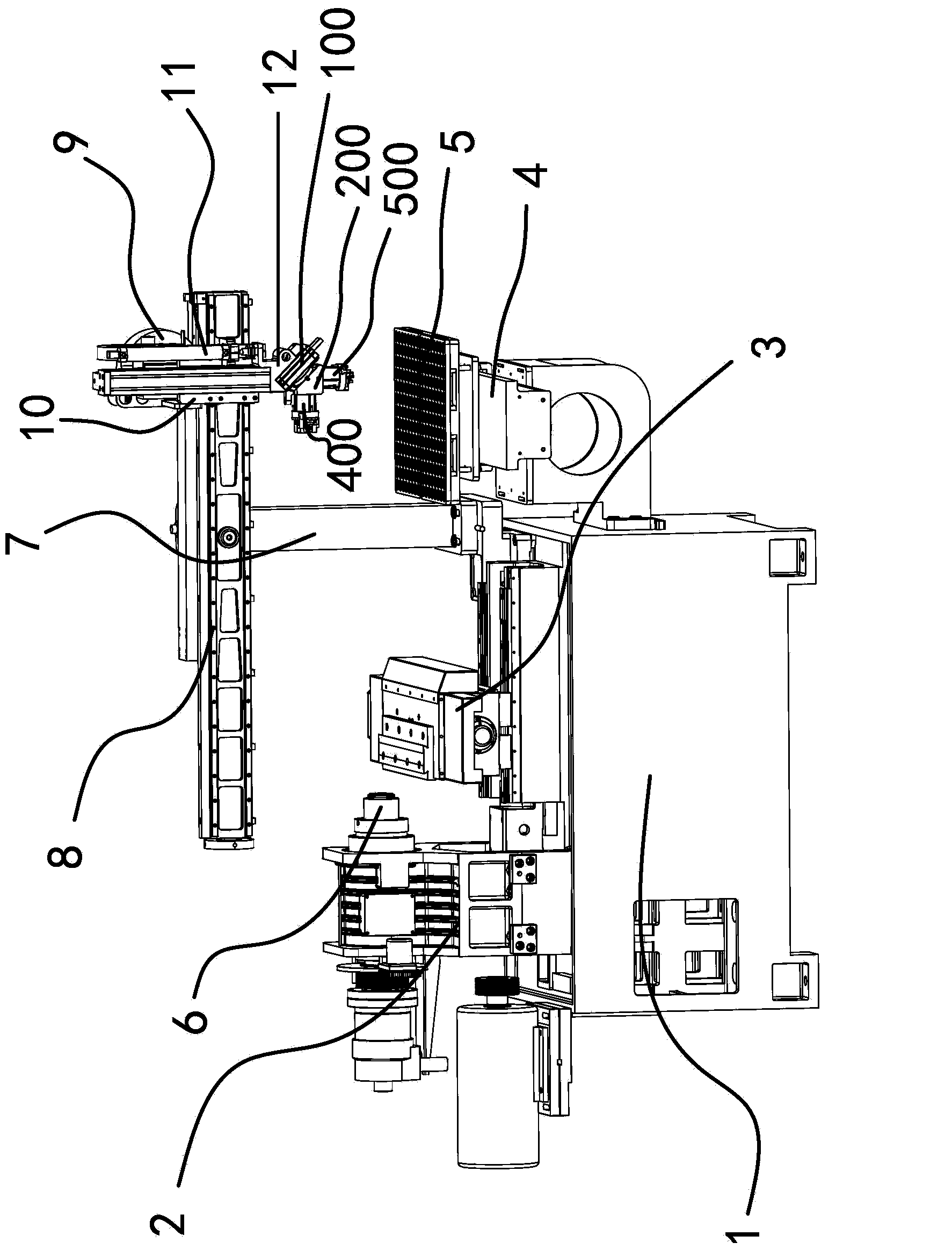
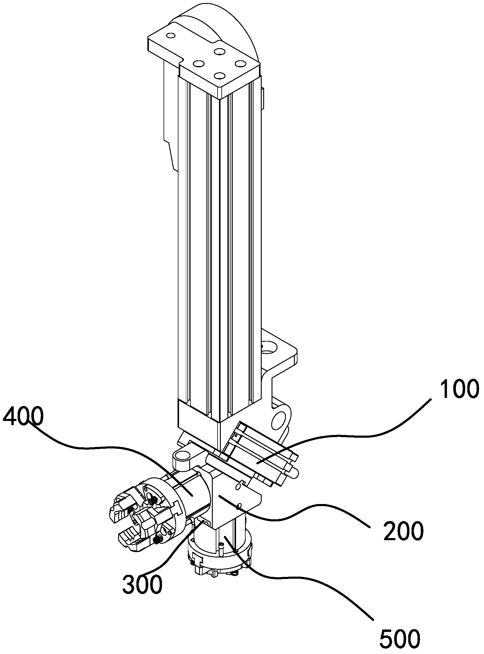
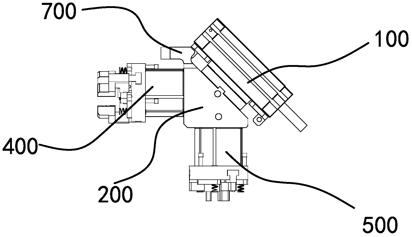
[0034] Such as Figure 1 to Figure 12 As shown, the palletizing manipulator includes a frame 1, on which an organic base 2, a workbench 3 and a material placement platform 4 for placing a code disc 5 are installed on the frame 1, and a main shaft 6 is installed on the frame 2, and the frame 1 is fixedly connected with a support frame 7 and is fixedly connected with a horizontally arranged main arm 8 on the support frame 7. A main motor 9 capable of laterally moving along the main arm 8 is installed on the main arm 8, and is fixedly connected with a main motor 9 on the main motor 9. Connecting seat 10 and a vertical lifting cylinder 11 is installed on the connecting seat 10, the end of the piston rod of the lifting cylinder...


PUM


Abstract

The invention provides a stacking manipulator, belongs to the technical field of machines and solves the problem that the feeding accuracy of the existing stacking manipulator is not high. The stacking manipulator comprises a rack, wherein a base, a working table and a material placing table are installed on the rack, a main shaft is installed on the base, a grabbing mechanism is installed on a lifting air cylinder, the grabbing mechanism comprises a rotary air cylinder and a rotating frame, an inclined side surface of the rotating frame is fixedly arranged on the rotary air cylinder, a first manipulator pneumatic gripper is installed on one right-angle side surface of the rotating frame, a second manipulator pneumatic gripper which can longitudinally move on the other right-angle side surface of the rotating frame is arranged on the right-angle side surface, each of the first manipulator pneumatic gripper and the second manipulator pneumatic gripper comprises a pedestal, a plurality of pneumatic grippers which are uniformly distributed around the axis of the pedestal are installed on the end surfaces of the pedestals, pushing plates for placing workpieces are arranged on the pedestals, and propelling mechanisms for enabling the pushing plates to move along axial direction of the pedestals are arranged between the pushing plates and the pedestals. The stacking manipulator has the advantages of convenience in operation and high accuracy.

Description

technical field [0001] The invention belongs to the technical field of machinery, and in particular relates to a stacking manipulator. Background technique [0002] With the development of the machinery manufacturing industry, there are more and more CNC lathes. In order to meet the requirements of multi-variety and small batch production and increase productivity, the CNC lathes are equipped with shaft parts loading and unloading systems, which are required to be able to transport bars and unload them of different sizes. For shafts and sheet parts, people use mechanical cutting automation equipment to process metal workpieces, which improves the processing efficiency and has high safety performance. [0003] At present, the most widely used loading and unloading device in mechanical cutting automation equipment is the rotary air claw device, which includes a rotary cylinder and a right-angled triangular prism-shaped rotary frame. Manipulator air claws are installed on the ...

Claims


Application Information

Patent Timeline
IPC IPC(8): B65G61/00
Inventor 杨云林
Owner 宁波宫铁智能科技有限公司
Why Eureka
Try Eureka