Combined defoaming and siphoning well and combined defoaming and siphoning method

A siphon well, combined technology, applied in waterway systems, drainage structures, water supply devices, etc., can solve problems such as aggravating foam, visual pollution, and affecting the environment of the sea area of ​​the power station, achieving uniform water flow and solving the effect of air bubbles.

Active Publication Date: 2014-12-24
CHINA INST OF WATER RESOURCES & HYDROPOWER RES
View PDF5 Cites 17 Cited by
  • Summary
  • Abstract
  • Description
  • Claims
  • Application Information

AI Technical Summary

Problems solved by technology

Most of these weirs use thin-walled weirs, practical weirs, and wide-crested weirs for free overflow drainage, resulting in strong water-air mixing in the process of water falling behind the weirs, resulting in light yellow foam that is not easy to burst, forming foam pollution areas , the splashed salt mist will also corrode the metal structures near the drain, and in order to reduce the

Method used


Image

  • Combined defoaming and siphoning well and combined defoaming and siphoning method
  • Combined defoaming and siphoning well and combined defoaming and siphoning method
  • Combined defoaming and siphoning well and combined defoaming and siphoning method

Examples


Example Embodiment

[0025] Example one:

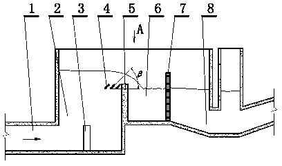
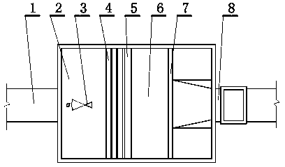
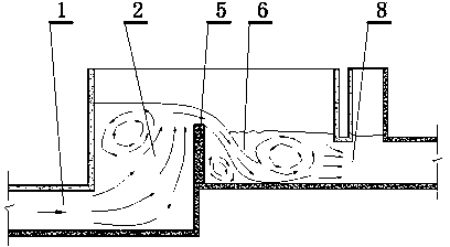
[0026] This embodiment is a combined defoaming siphon well, such as figure 1 , 2 Shown. This embodiment includes at least one siphon well assembly. The siphon well assembly includes a shaft 2 with a water inlet culvert 1. The shaft is connected to an overflow tank 6, and the overflow tank is connected to the vertical shaft. An overflow weir 5 is provided in the middle, the overflow weir is arranged on the side of the shaft opposite to the water inlet square culvert, and the side of the overflow pool opposite to the overflow weir is provided with a water delivery square culvert 8 , Between the inlet culvert and the overflow weir at the bottom of the shaft, a diversion pier 3 is set on the central axis facing the direction of the water inlet culvert, and the overflow weir is on the side of the shaft, close to the overflow weir A horizontally arranged weir front guide grid 4 is arranged at the top position, and at least one piece of defoaming is arranged verti...

Example Embodiment

[0038] Embodiment two:

[0039] This embodiment is an improvement of the first implementation. It is about the refinement of the first embodiment of the siphon well assembly. This embodiment includes two siphon well assemblies arranged side by side, and the siphon well assemblies share a side wall. The central axis of the water delivery culvert in the direction of water is offset to the shared side wall, such as Figure 5 Shown.

[0040] In this embodiment, a power station uses two side-by-side siphon well combinations, and when the drainage changes in winter and summer and the external water level changes greatly, two or three siphon well combinations can be used to adapt to these changes. . However, if there are too many siphon wells, the engineering cost will increase exponentially, which is a problem that must be considered. Nowadays, a power station basically uses a combination, so that when half of the units are overhauled, a siphon well combination will not affect the powe...

Example Embodiment

[0041] Embodiment three:

[0042] This embodiment is an improvement of the above-mentioned embodiment, and is a refinement of the above-mentioned embodiment on the diversion pier. The horizontal cross-sectional shape of the diversion pier in this embodiment is an isosceles triangle. The top angle of the isosceles triangle is the water-incoming surface and the bottom side is the back water surface. The height of the diversion pier is from the bottom of the siphon well to the outlet of the water-inlet culvert. The highest point is flush, such as figure 1 , 2 Shown.

[0043] The function of the triangular diversion pier is to divert the water body at the outlet of the inlet square culvert to both sides, avoiding the water body from being concentrated in the middle of the shaft and causing excessive water body fluctuations.

[0044] The triangle is an isosceles triangle, and its apex angle can be selected within a certain range. If the angle is too large, it will have a wall-like effect...


PUM


Abstract

The invention relates to a combined defoaming and siphoning well and a combined defoaming and siphoning method. The combined defoaming and siphoning well comprises at least one siphoning well combined body, wherein the siphoning well combined body comprises a vertical well with a water inlet square culvert, a spill pit, an overflow weir, a spill pit and a water conveying square culvert; a diversion pier is arranged between the water inlet square culvert and the overflow weir at the bottom of the vertical well and is opposite to the central axis of the water outlet direction of the water inlet square culvert; the overflow weir is arranged on one side of the vertical well, and the part, adjacent to the top, of the overflow weir is provided with front weir diversion grids arrayed horizontally; at least one vertically-arranged defoaming orifice plate used for dividing the spill pit into two parts is arranged between the overflow weir in the spill pit and the outlet of the water conveying square culvert; the bottom, connected with the water outlet square culvert, of the spill pit inclines downwards. The siphoning well is provided with the diversion pier and the front weir diversion grids, so that the nappe over weir is uniform and stable; the defoaming orifice plate is used for energy dissipation and flow equalization, so that the flowing speed of waterflow after jumping is reduced; the inlet elevation of the water conveying square culvert is reduced, so that bubbles are prevented from entering the water conveying square culvert. By virtue of the measures, the bubble problem of the drainage siphoning well is solved.

Description

technical field [0001] The invention relates to a combined defoaming siphon well and method, which is a hydraulic facility and method, and an environmental protection facility and method. Background technique [0002] Coastal thermal power or nuclear power plants that adopt the direct current cooling method generally have drainage siphon wells to reduce the head of the water pump by using the siphon effect and save energy. In the siphon well, there is an outflow weir whose top elevation exceeds the average tidal level, so as to reduce the influence of the tide level change in the open sea on the upstream section of the siphon well. Most of these weirs use thin-walled weirs, practical weirs, and wide-crested weirs for free overflow drainage, resulting in strong water-air mixing during the water drop behind the weirs, resulting in hard-to-break yellowish foam, forming foam pollution areas , the splashed salt mist will also corrode the metal structures near the drain, and in o...

Claims


Application Information

Patent Timeline
IPC IPC(8): E03F5/00E03F5/20
Inventor 纪平付辉刘召平杨开林郭新蕾郭永鑫王涛施春蓉赵懿珺曾利秦晓张强
Owner CHINA INST OF WATER RESOURCES & HYDROPOWER RES
Why Eureka
Try Eureka