
Transonic gas film cooling hole

A film cooling, transonic technology, which is applied to the supporting elements of blades, engine elements, machines/engines, etc., can solve the problem of accelerating cold air to supersonic speed, and achieve the effect of good cooling effect.

Inactive Publication Date: 2014-12-24
NORTHWESTERN POLYTECHNICAL UNIV
View PDF5 Cites 10 Cited by
  • Summary
  • Abstract
  • Description
  • Claims
  • Application Information

AI Technical Summary

Problems solved by technology

[0005] In order to avoid the deficiencies in the prior art and overcome the problem that the air film hole type cannot accelerate the cold air flowing through the hole from subsonic to supersonic, the present invention proposes a transonic air film cooling hole

Method used


Image

  • Transonic gas film cooling hole
  • Transonic gas film cooling hole
  • Transonic gas film cooling hole

Examples


Embodiment 1

[0019] This embodiment is a transonic air film cooling hole structure on a turbine working blade of a certain type of engine.

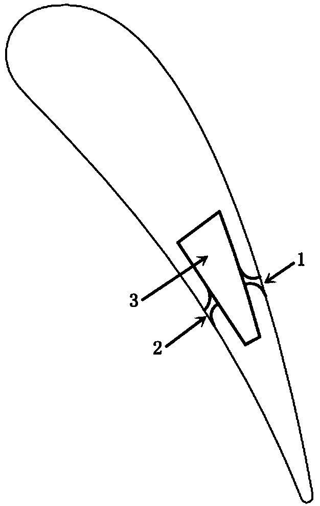
[0020] refer to figure 1 , figure 2 , image 3 In this embodiment, a transonic film cooling hole 1 is provided on the suction surface of the engine turbine blade near the trailing edge, and the suction surface film cooling hole 1 communicates with the internal cooling channel 3 of the turbine blade.

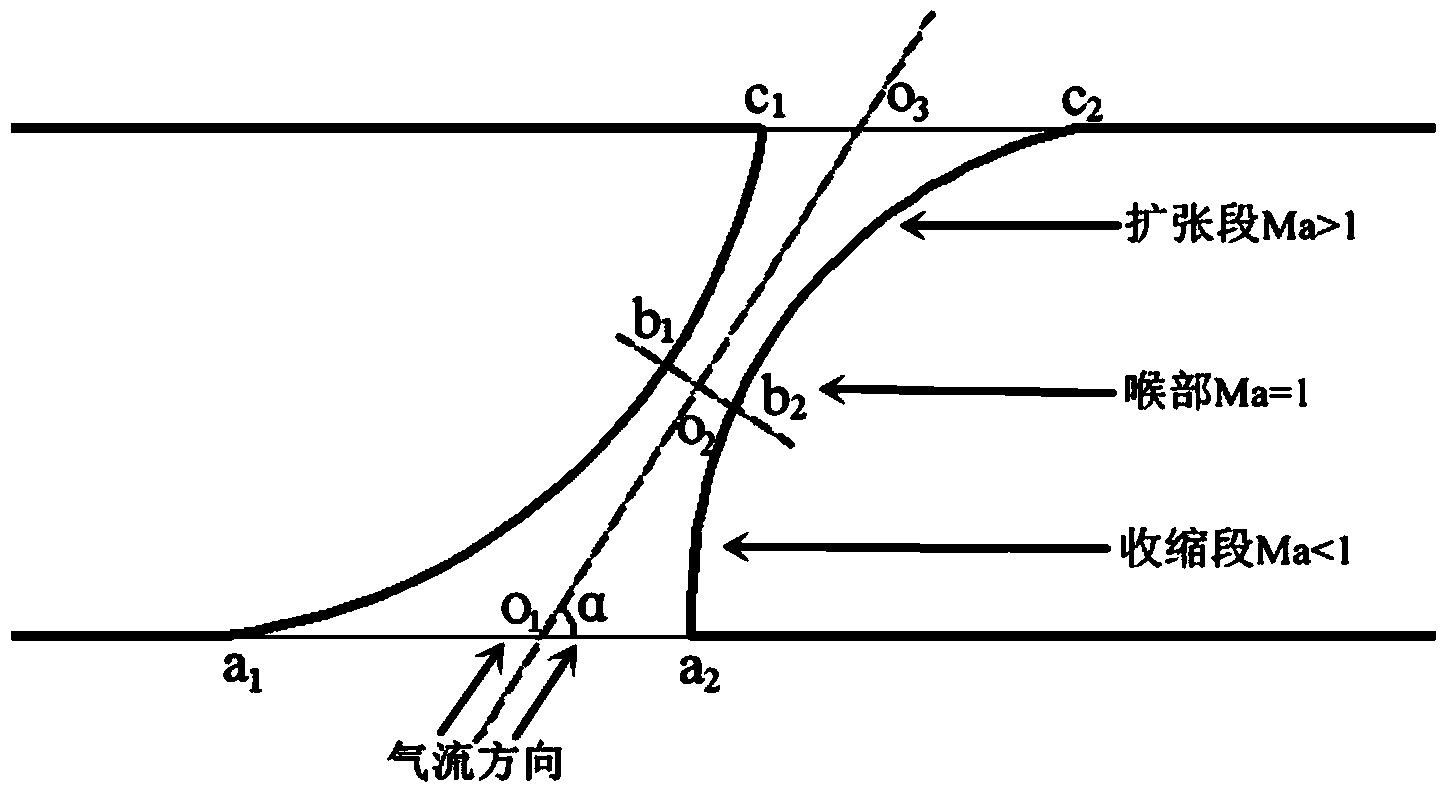
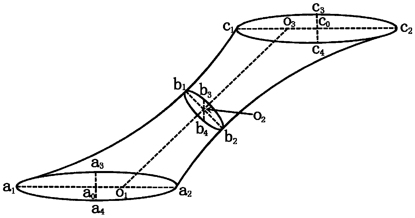
[0021] In this embodiment, the overall structure of the transonic film cooling hole on the suction surface is divided into a constriction section, a throat section and an expansion section. There is an included angle α between the center line of the transonic film cooling hole on the suction side and the surface of the blade, and the included angle α is taken as 45°. The entrance section of the transonic film cooling hole on the suction side is elliptical, a 1 with a 0 The distance between them is the length s of the semi-major axis of the ellipse o...

Embodiment 2

[0032] This embodiment is a transonic air film cooling hole structure on a turbine working blade of a certain type of engine.

[0033] refer to figure 1 , figure 2 , image 3 In this embodiment, a pressure surface transonic film cooling hole 2 is provided on the pressure surface of the engine turbine blade near the trailing edge, and the pressure surface film cooling hole 2 communicates with the internal cooling channel 3 of the turbine blade.

[0034] In this embodiment, the overall structure of the transonic film cooling hole on the pressure surface is divided into a constriction section, a throat section and an expansion section. There is an angle α between the center line of the transonic film cooling hole on the pressure surface and the surface of the blade, and the angle α is taken as 60°. The inlet cross section of the transonic film cooling hole on the pressure surface is elliptical, a 1 with a 0 The distance between them is the length s of the semi-major axis of ...


PUM


Abstract

The invention discloses a transonic gas film cooling hole. An included angle between the center line of a gas film cooling hole in a suction surface and a gas film cooling hole in a pressure surface of a turbine blade and the surface of the blade is 30-60 degrees; the overall structure of the transonic gas film cooling hole is divided into a shrinkage section, a throat part and an expansion section; the length I1 of the center line of the shrinkage section of the transonic gas film cooling hole is 6-10 times of the radius of the throat part; the mold line of the wall surface is calculated from the inlet of the gas film cooling hole to the throat part by using a vito shinseki formula; the throat part is a transition section of cold air from subsonic speed to supersonic speed; the sectional area of the throat part is determined by using the cold air flow; smooth transition is carried out from the throat part to the expansion section; the smooth wall surface of the expansion section is obtained by adopting a basically same curvature radius; the semi-apex angle beta of the expansion section is 4-6 degrees; the length I2 of the center line of the expansion section is determined through the semi-apex angle. The transonic gas film cooling hole is designed into a shrinkage and expansion shape, and when the cold air flows through the gas film hole, the flow rate can be increased to supersonic speed from subsonic speed, so that the cooling effect of the gas film is ensured.

Description

technical field [0001] The invention belongs to the technical field of aeroengine turbine blades, and in particular relates to a transonic air film cooling hole. Background technique [0002] With the rapid development of aero-engines, the turbine inlet temperature continues to increase, and the turbine inlet temperature of a first-stage engine with a thrust-to-weight ratio of 10 has reached 1900K-2000K, which has far exceeded the heat resistance limit of turbine blade materials. At present, air film cooling technology is widely used in aero-engines to cool turbine blades, that is, part of the gas extracted from the compressor is introduced into the blades as cold air to effectively cool the inner surface of the blades, and at the same time a part of the cold air passes through the air film holes on the blade wall. When it is sprayed out, under the action of the main flow outside the blade, the cold air forms a thin film of cold air on the surface of the blade, which isolate...

Claims


Application Information

Patent Timeline
Patent Type & Authority Applications(China)
IPC IPC(8): F01D5/18
Inventor 朱惠人苏文超
Owner NORTHWESTERN POLYTECHNICAL UNIV
Learn More