Inclined shaft type plunger pump device

A plunger pump and oblique shaft technology, which is applied in the field of oblique axis plunger pump devices, can solve problems such as the inability to meet the needs of development, and achieve the effects of small friction loss, strong self-priming ability and firm connection

Inactive Publication Date: 2014-12-24
龙勇军
View PDF0 Cites 6 Cited by
  • Summary
  • Abstract
  • Description
  • Claims
  • Application Information

AI Technical Summary

Problems solved by technology

However, the existing pump performance still cannot meet the needs of development.

Method used


Image

  • Inclined shaft type plunger pump device

Examples


Embodiment 1

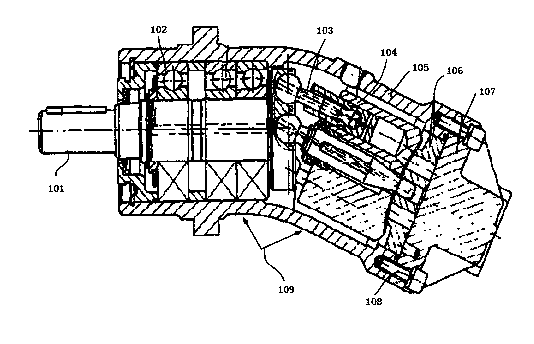
[0021] figure 1 A schematic structural view of an inclined-axis plunger pump device according to an embodiment of the present invention is shown. like figure 1 An inclined-axis plunger pump device shown includes a main shaft 101, a bearing 102, a connecting rod plunger pair 103, a cylinder block 104, a casing 105, a flow plate 106 and a rear cover 107, and one end of the rotating shaft 101 passes through the bearing 102 is connected to the inner wall of one end of the housing 105, the housing 105 is curved, one end of the rotating shaft 101 located in the housing 105 is connected to a connecting rod plunger pair 103, and the connecting rod plunger pair 103 is connected to the cylinder body 104 , the cylinder body 104 is connected with the valve plate 106, and the other end of the housing 105 is provided with a rear cover 107, through which the connecting rod plunger pair 103, the cylinder body 104 and the valve plate 106 are sealed in Inside the casing 105 .

[0022] The re...

Embodiment 2

[0029] The main shaft is supported on three bearings, one of which can also be a double angular contact ball bearing, which can withstand both large axial force and certain radial force. The other bearing is a deep groove ball bearing, which mainly bears radial force. The bearing set can ensure the stable high-speed rotation of the main shaft and has a long service life.

[0030] Disc springs can be set at the bearings (can be close to figure 1 The left bearing shown) is used to ensure the pretightening force of the paired double angular contact ball bearings, and at the same time, it can also make the bearings run normally with low noise when rotating at high speed.

[0031] The end cap can seal the gap between the end cap and the housing through an O-ring to prevent leakage. The connecting rod and plunger pair can be connected together by radial rolling of two parts, the connecting rod and the plunger. The large ball head of the connecting rod is pressed in the ball socke...


PUM


Abstract

The invention discloses an inclined shaft type plunger pump device. The inclined shaft type plunger pump device comprises a main shaft, a bearing, a connecting rod plunger pair, a cylinder, a shell, a valve plate and a back cover, wherein one end of a rotating shaft is connected with the inner wall of one end of the shell through the bearing; the shell is bent; one end of the rotating shaft in the shell is connected with the connecting rod plunger pair; the connecting rod plunger pair is connected with the cylinder; the cylinder is connected with the valve plate; the back cover is arranged at the other end of the shell; and the connecting rod plunger pair, the cylinder and the valve plate are sealed in the shell through the back cover. In the inclined shaft type plunger pump device, the lateral force of the plunger is smaller than the lateral force of the plunger of a straight shaft type pump, so that the frictional loss caused by the lateral force is low; and the connection between a connecting rod bulb and the main shaft is firm, so that the self-priming capacity is stronger.

Description

technical field [0001] The invention relates to the technical field of plunger pumps, in particular to an inclined-axis plunger pump device. Background technique [0002] my country's production of inclined-axis plunger pumps began in 1960, but the variety and quantity were relatively small. In 1978, a hydraulic pump factory in Beijing introduced A2F quantitative pumps, A6V variable motors, A7V There are more than 500 specifications and varieties of four series of variable pumps and A8V variable variable double pumps. Subsequently, Shanghai Hydraulic Pump Factory introduced a quantitative pump with A2F6.1 structure. At present, my country has been able to produce inclined-axis pumps of various specifications and variable types with a displacement ranging from 10ml / r to 500ml / r, a rated pressure of 35MPa, and a maximum pressure of 45MPa. However, the performance of the existing pumps still cannot meet the needs of development. Contents of the invention [0003] The invent...

Claims


Application Information

Patent Timeline
Patent Type & Authority Applications(China)
IPC IPC(8): F04B1/20
Inventor 龙勇军
Owner 龙勇军
Why Eureka
Try Eureka