
Multistage cantilever compressor

A compressor and cantilever technology, applied in the field of cantilever multi-stage compressors, can solve problems such as affecting the compression and circulation efficiency of the compressor, increasing the cost of the compressor, and having a complex compressor structure, achieving simple structure, reduced flow loss, and low cost. Effect

Inactive Publication Date: 2014-12-24
CHONGQING MIDEA GENERAL REFRIGERATING EQUIP
View PDF8 Cites 7 Cited by
  • Summary
  • Abstract
  • Description
  • Claims
  • Application Information

AI Technical Summary

Problems solved by technology

If the compression part is single-stage compression, the gas flow velocity in the compression part is faster, resulting in greater flow loss, which affects the compression and cycle efficiency of the compressor.
If the drive part adopts a structure in which the rotor is centered at both ends, it will lead to a complex structure of the compressor, troublesome assembly, and a substantial increase in the cost of the compressor

Method used


Image

  • Multistage cantilever compressor

Examples


Embodiment Construction

[0028]Embodiments of the present invention are described in detail below, examples of which are shown in the drawings, wherein the same or similar reference numerals designate the same or similar elements or elements having the same or similar functions throughout. The embodiments described below by referring to the figures are exemplary only for explaining the present invention and should not be construed as limiting the present invention.

[0029] In describing the present invention, it should be understood that the terms "center", "longitudinal", "transverse", "upper", "lower", "front", "rear", "left", "right", " The orientations or positional relationships indicated by "vertical", "horizontal", "top", "bottom", "inner" and "outer" are based on the orientations or positional relationships shown in the drawings, and are only for the convenience of describing the present invention and Simplified descriptions, rather than indicating or implying that the device or element refer...


PUM


Abstract

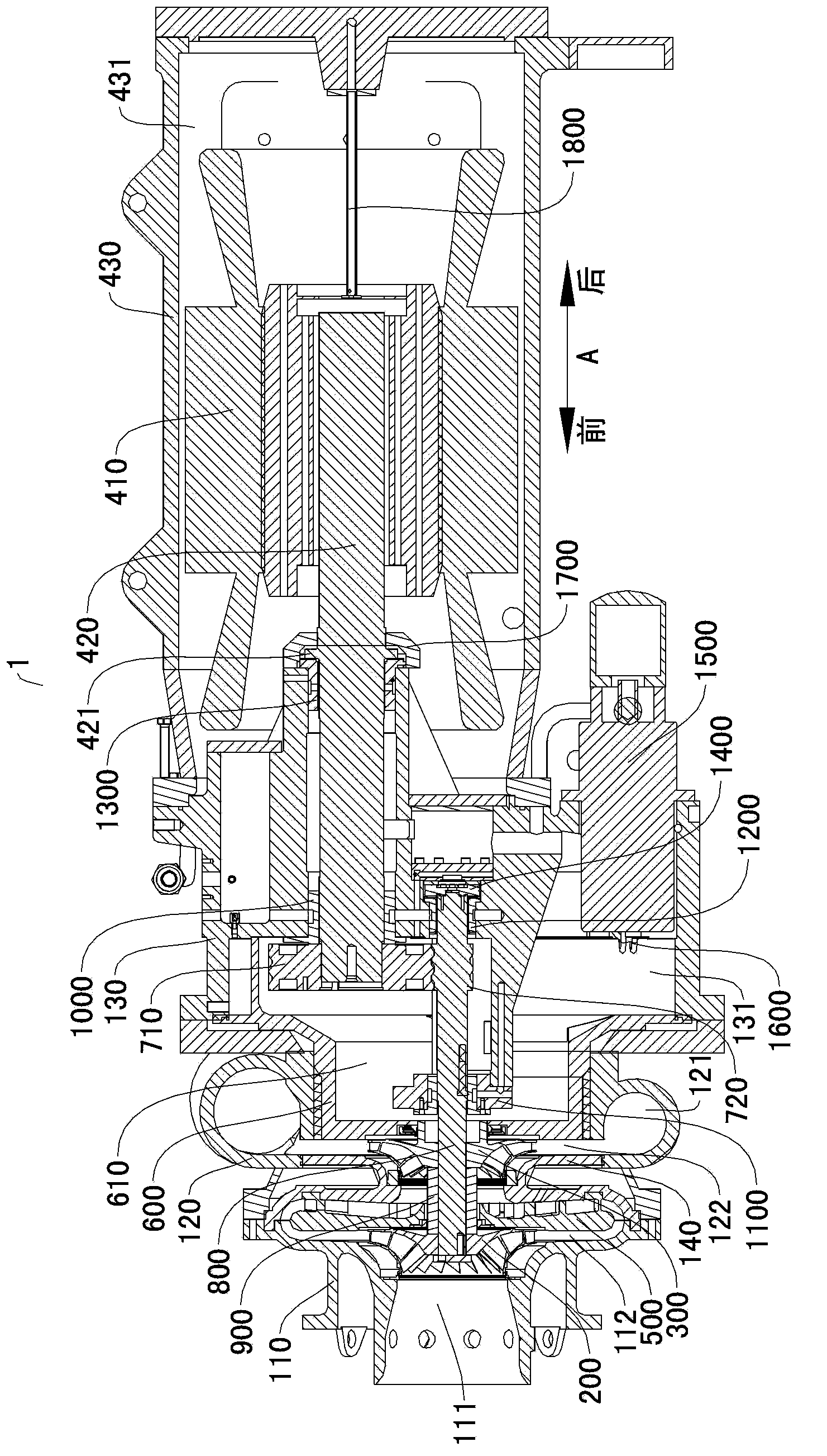
The invention discloses a multistage cantilever compressor. The multistage cantilever compressor comprises a shell, a plurality of impellers and a motor. A plurality of compression cavities are formed in the shell which is provided with an inlet and an outlet, the forefront compression cavity is communicated with the outside through the inlet, and the hindmost compression cavity is communicated with the outside through the outlet. The plurality of impellers are correspondingly and rotatably arranged in the plurality of compression cavities, each impeller is internally provided with an air passage, and the air passages of the impellers are communicated. The motor is arranged on the shell and comprises a stator and a rotor, the front portion of the rotor is rotatably supported on the shell and respectively connected with the plurality of impellers to enable the motor to drive the impellers to rotate, and the rear portion of the rotor is rotatably suspended in the stator. The multistage cantilever compressor has the advantages of high circulation efficiency, simple structure, simplicity in assembly, low cost and the like.

Description

technical field [0001] The invention relates to the field of gas compression, in particular to a cantilever multistage compressor. Background technique [0002] In a centrifugal compressor, the kinetic energy of the gas is converted into pressure energy through the rotation of the impeller to realize the function of compressing the gas. Existing centrifugal compressors include air intake, compression, exhaust and drive. The overall structure is single-stage cantilever or double-supported, and multi-stage double-supported. If the compression part is single-stage compression, the gas flow velocity in the compression part is relatively fast, resulting in large flow loss and affecting the compression and cycle efficiency of the compressor. If the driving part adopts a structure in which the rotor is centered at both ends, the structure of the compressor will be complicated, the assembly will be troublesome, and the cost of the compressor will be greatly increased. Contents o...

Claims


Application Information

Patent Timeline
IPC IPC(8): F04D17/12F04D29/62H02K7/14
Inventor 张海洲茹志鹏吴昕刘平平张恒海李镇杉辜永刚吴文辉杨志华王永
Owner CHONGQING MIDEA GENERAL REFRIGERATING EQUIP
Learn More