A buncher

A continuously variable transmission, distance sensor technology, applied in the direction of vehicle gearbox, transmission control, transmission components, etc., can solve problems such as inability to torque control

Inactive Publication Date: 2014-12-24
HONDA MOTOR CO LTD
View PDF5 Cites 4 Cited by
  • Summary
  • Abstract
  • Description
  • Claims
  • Application Information

AI Technical Summary

Problems solved by technology

[0018] As a result, in conventional continuously variable transmissions, it may not be possible to control the actual gear ratio and the torque transmitted to the output shaft with high precision

Method used


Image

  • A buncher
  • A buncher
  • A buncher

Examples


no. 1 Embodiment approach

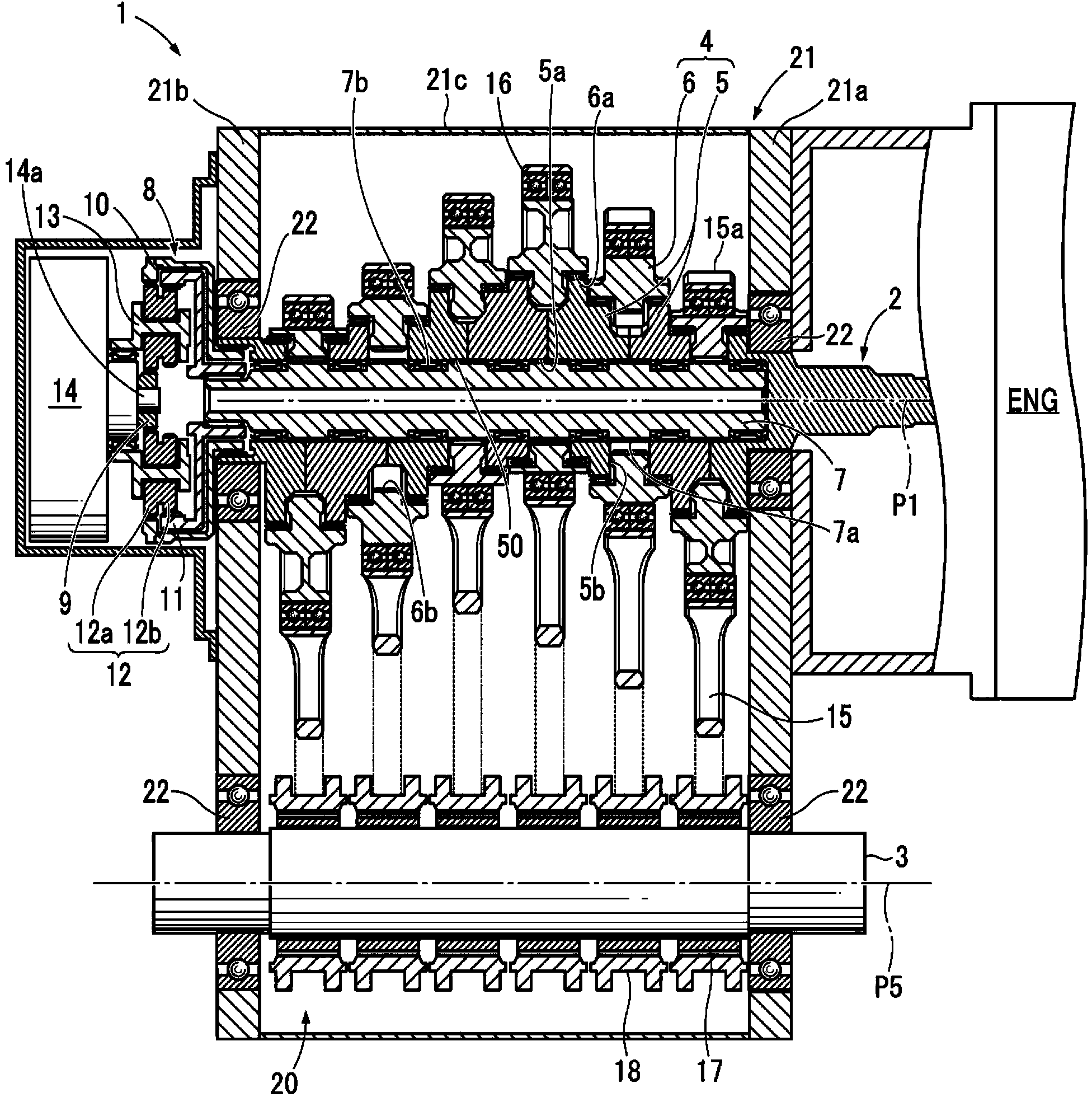
[0048] refer to Figure 1 to Figure 6 , the continuously variable transmission of the first embodiment will be described.

[0049] First, refer to figure 1 and figure 2 The structure of the continuously variable transmission 1 of this embodiment is demonstrated.

[0050] Such as figure 1 As shown, the continuously variable transmission 1 of the present embodiment includes: an input part 2; an output shaft 3 arranged parallel to the rotation center axis P1 of the input part 2; on the rotation center axis P1.

[0051] The input unit 2 is rotated around the rotation center axis P1 by being transmitted with a driving force from an engine ENG (travel driving source) as a main driving source. Furthermore, as the main drive source, an electric motor or the like may be used in addition to the internal combustion engine.

[0052] The output shaft 3 transmits rotational power to drive wheels (not shown) of the vehicle via a differential gear (not shown). Also, a propeller shaft ...

no. 2 Embodiment approach

[0119] refer to Figure 7A , 7B , the continuously variable transmission of this embodiment will be described. Wherein, the continuously variable transmission of the present embodiment differs from the continuously variable transmission of the first embodiment only in the swing link and the detected component, so only the swing link and the detected component will be described in detail. In addition, the same code|symbol is attached|subjected to the same structure as the continuously variable transmission of 1st Embodiment, and their description is abbreviate|omitted.

[0120] Such as Figure 7A , 7B As shown, the swing link 18 has a swing end portion 18 a connected to the link 15 and an annular portion 18 d pivotally supported by the output shaft 3 .

[0121] In addition, two attachment pins 25 are provided on the outer peripheral surface of the annular portion 18 d of the swing lever 18 , and the member to be detected 26 is slidably attached to the attachment pins 25 . ...


PUM


Abstract

The invention provides a buncher which can highly precisely control a gear ratio and a torque transmitted to an output shaft. The buncher (1) comprises a distance sensor (23) used for detecting the distance (x) from the distance sensor to a detected portion (18e) of an oscillating bar (18) which can be supported on an output shaft (3) in a rotary shaft bearing mode and an ECU (24) which calculates a phase position (theta) of the oscillating bar (18) based on a value detected by the distance sensor (23) and calculating a rotation radius of a rotating disk (6) based on the phase position (theta).

Description

technical field [0001] The present invention relates to a four-joint linkage type continuously variable transmission using a crank-rocker mechanism. Background technique [0002] Conventionally, there is known a four-joint link mechanism type continuously variable transmission comprising: an input shaft to which a driving force is transmitted from a main drive source such as an engine (driving source for traveling); The rotation center axis of the input shaft is parallel; and a plurality of crank-rocker mechanisms (for example, refer to Patent Document 1). [0003] In the continuously variable transmission described in Patent Document 1, the crank-rocker mechanism has: a rotation radius adjustment mechanism provided with a rotation portion that can rotate integrally with the input shaft and can freely adjust the rotation radius of the rotation portion; a rod provided with a swinging end portion and pivotally supported on the output shaft freely; and a connecting rod, one en...

Claims


Application Information

Patent Timeline
Patent Type & Authority Applications(China)
IPC IPC(8): F16H21/28
CPCF16H21/28F16H57/00F16H59/00F16H2200/00F16H2710/24
Inventor 西村优史
Owner HONDA MOTOR CO LTD
Why Eureka
Try Eureka