Transformer oil gassing device

A technology for transformer oil and gas evolution, applied in the field of electric power engineering, can solve the problems of high equipment cost and unfavorable wide-scale popularization and use.

Inactive Publication Date: 2014-12-24
HANGZHOU SHENHAO TECH
View PDF13 Cites 3 Cited by
  • Summary
  • Abstract
  • Description
  • Claims
  • Application Information

AI Technical Summary

Problems solved by technology

This device can separate gas from oil, but the equipmen

Method used


Image

  • Transformer oil gassing device

Examples


Embodiment Construction

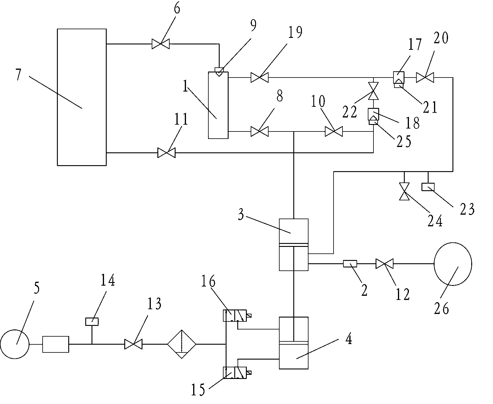
[0010] See attached picture. This embodiment includes a sampler 1, a quantitative tube 2, a vacuum chamber 3, a pneumatic chamber 4 and a compressor 5. The upper end of the sampler 1 is connected to the transformer 7 through an oil inlet valve 6, and the lower end of the sampler 1 is connected through a degassing communication valve 8. Connected to the upper end of the vacuum chamber 3, the sampler 1 has a first liquid level sensor 9; the upper end of the vacuum chamber 3 is also connected to the transformer 7 through the cylinder valve 10 and the oil discharge valve 11, and the lower end of the vacuum chamber 3 is connected to the pneumatic valve through the piston rod. The chamber 4 is matched; the outer end of the quantitative tube 2 is connected with the carrier gas valve 12, and the inner end is connected with the vacuum chamber 3; this embodiment also includes a certain gas valve 13 and a pressure controller 14; the pressure controller 14 is connected to the air outlet o...


PUM


Abstract

The invention discloses a transformer oil gassing device which comprises a sampler, a quantifying pipe, a vacuum chamber, a pneumatic chamber, a compressor, a fixed gas valve and a pressure controller, wherein the upper end of the sampler is connected with a transformer through an oil inlet valve, and the lower end of the sampler is connected with the upper end of the vacuum chamber through a degassing communicating valve; the upper end of the vacuum chamber is connected with the transformer through an air cylinder valve and an oil discharge valve, and the lower end of the vacuum chamber is matched with the pneumatic chamber through a piston rod; the outer end of the quantifying pipe is connected with a carrier gas valve, and the inner end of the quantifying pipe is connected with the vacuum chamber; the pressure controller is connected with the gas outlet of the compressor, the inlet end of the fixed gas valve is connected with the pressure controller, and the outlet end of the fixed gas valve is connected with the pneumatic chamber through an air cylinder upward valve and an air cylinder downward valve. According to the transformer oil gassing device, an oil pump is eliminated, so that the equipment cost is greatly reduced; due to the elimination of the oil pump, the oil getting way is changed, the forced oil circulation is no longer used, instead an oil sample in an oil inlet pipeline is extracted by the vacuum chamber, oil is discharged after being separated from gas, and a new oil sample is obtained.

Description

technical field [0001] The invention belongs to the technical field of electric power engineering, in particular to a transformer oil degassing device. Background technique [0002] For high-voltage power transmission and transformation equipment such as high-voltage transformers, mineral oil is used to achieve the purpose of insulation, arc extinguishing and cooling. During the working process of these equipment, due to overheating, discharge, arcing and other reasons, it will form a cracking effect on mineral oil and produce fault characteristic gases such as carbon monoxide, hydrogen and acetylene. Therefore, the working status of the corresponding equipment can be evaluated by monitoring the concentration and change trend of these faulty characteristic gases. [0003] Because the above-mentioned fault characteristic gases can be fully dissolved in mineral oil, their concentration is very low, so it is necessary to separate these gases from mineral oil through a special ...

Claims


Application Information

Patent Timeline
IPC IPC(8): G01N1/34
Inventor 陈如申黎勇跃
Owner HANGZHOU SHENHAO TECH
Why Eureka
Try Eureka