Multi-pole connector

A connector and multi-pole technology, applied in the direction of connection, conductive connection, and parts of connection devices, can solve the problems of shape change, complicated wiring, labor and time consumption, etc., and achieve high strength, efficient assembly, and easy assembly Effect

Inactive Publication Date: 2014-12-24
SMK CO LTD
View PDF8 Cites 7 Cited by
  • Summary
  • Abstract
  • Description
  • Claims
  • Application Information

AI Technical Summary

Problems solved by technology

[0010] However, in the case of using the conventional unipolar coaxial connector as described above, it is necessary to mount and wire on the board according to the connector, so that there is a problem that the wiring is complicated and the connection operation is labor-intensive and time-consuming. configuration, occupying a certain amount of space on the substrate, which becomes a factor hindering the miniaturization of electronic equipment
[0011] In addition, from the viewpoint of board design, there is a demand for a multi-layer arrangement in which a plurality of vias are arranged in the vertical direction on the mounting board, and this request cannot be met by using a conventional single-pole coaxial connector. Corresponding question
[0012] On the other hand, in the multi-polarization of the interface, the color separation according to the housing may improve the work efficiency visually. There is a problem that it cannot correspond to such color separation according to the shell
[0013] In addition, the specification of the form of the connecting convex portion that is integrally protruded from the front portion of the housing and fits into the connecting concave portion of the mating side housing differs depending on the housing shape of the mating side connector, etc. In the case-integrated multi-pole connector, the housing shape of the counterpart connector, etc., may not correspond to the position of one of the engaging claws in the plurality of connecting protrusions, and the other shapes may be changed to match the current connecting protrusions. The situation of different specifications, not suitable for a variety of small batch production

Method used


Image

  • Multi-pole connector
  • Multi-pole connector
  • Multi-pole connector

Examples


Embodiment Construction

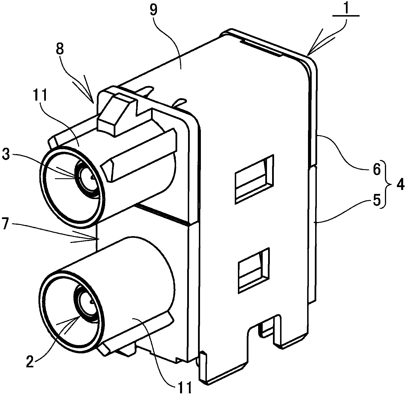
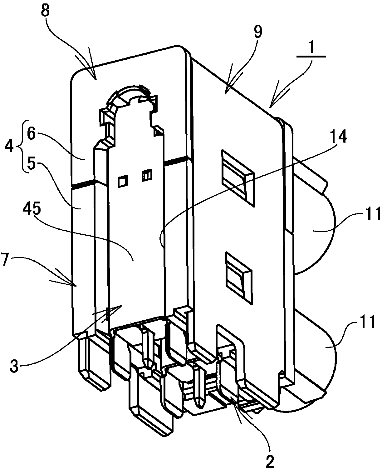
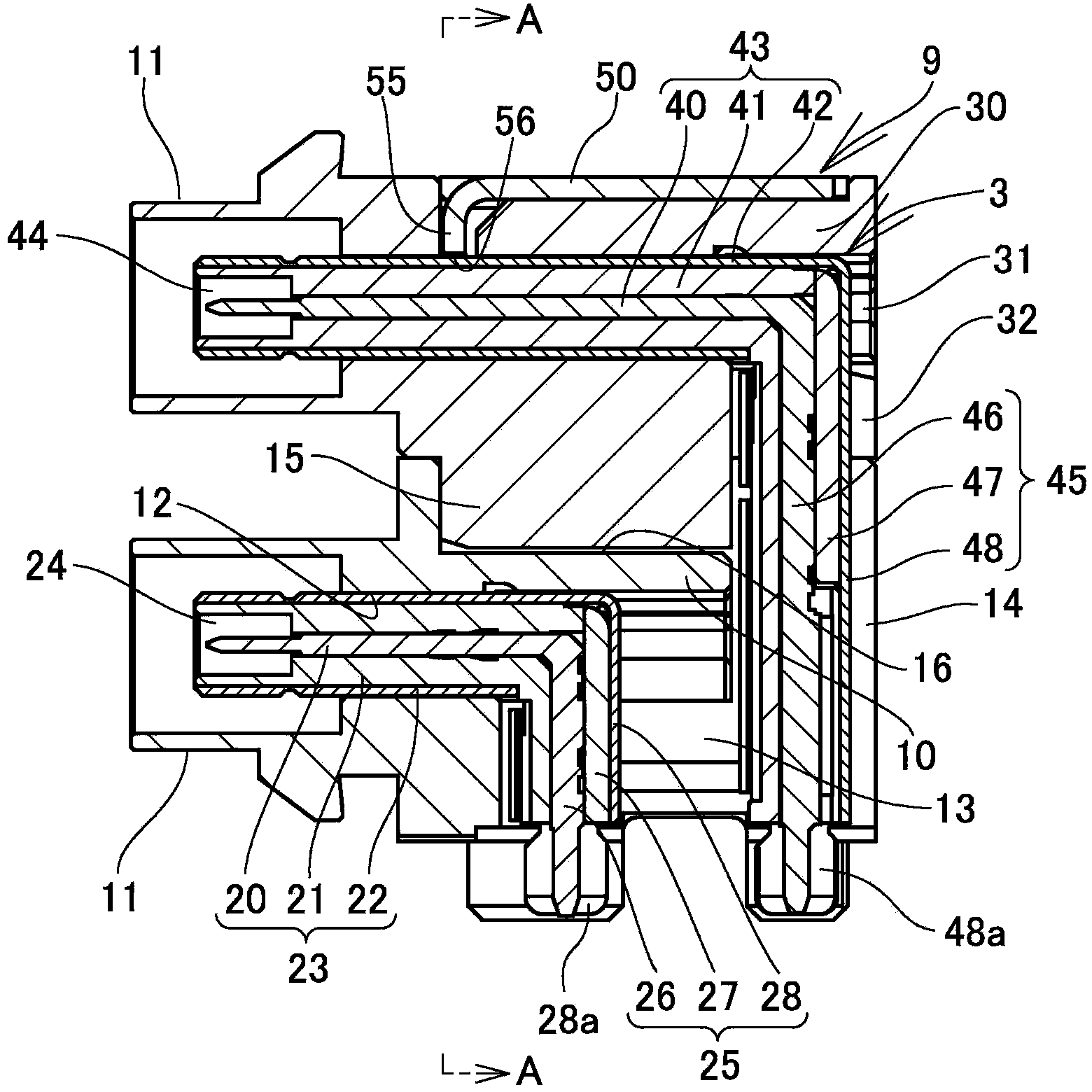
[0052] Next, based on Figure 1 to Figure 15 The illustrated embodiment illustrates the implementation of the multi-pole connector of the present invention.

[0053] This embodiment is described by taking the bipolar coaxial connector arranged in the upper and lower layers as an example, and the symbol 1 in the figure is a multi-pole connector.

[0054] In addition, in this embodiment, the vertical direction relative to the surface of the substrate on which the multipolar connector 1 is mounted (hereinafter referred to as the mounting substrate) is referred to as the up-down direction, and the substrate side is described as the bottom. The connection direction between the connector 1 and the connector on the opposite side is referred to as the front-rear direction when the surfaces are parallel, and the opposite side is described as the front.

[0055] Such as Figure 1 to Figure 5 As shown, the multi-pole connector 1 is the following multi-pole coaxial connector, which is e...


PUM


Abstract

The invention provides a multi-pole connector which can correspond with multiple poles of an interface and realizes space saving of an interface part. Furthermore the multi-pole connector can correspond with a multilayer configuration in which a plurality of conductor connecting parts are configured on a mounting substrate in a vertical direction. The multi-pole connector is provided with a plurality of divided connectors (7,8) which are obtained through respectively holding conductors (2,3) on divided housings (5,6) that are divided from the housing (4) and have different shapes. A joint end surface part of one divided housing (5) in the divided housings (5,6) which are adjacent with each other is provided with a key embedding part (16) for insertion of a connecting key (15). Through embedding the connecting key (15) into the key embedding part (16), the connecting key (15) is clamped between the joint end surface parts in a manner of bestriding the joint end surface parts, thereby joining the two divided housings (5,6), thereby connecting the divided connectors (7,8) which are adjacent with each other.

Description

technical field [0001] The present invention relates to a multi-pole connector, which is a connector such as a vehicle-mounted coaxial connector, in which a plurality of conductor connection parts connected to conductors on the opposite side are arranged on the front surface. Background technique [0002] For the connection between the information communication antenna and the on-vehicle equipment, a coaxial connector with excellent high-frequency performance is used, and the antenna and the on-vehicle equipment are electrically connected via the coaxial connector mounted on the board mounted on the on-vehicle equipment. [0003] On the other hand, in recent years, with the popularization of digital communication, etc., the efficiency of the connection work between the antenna and the vehicle-mounted equipment and the multi-polarization of the interface are required. In other words, a plurality of unipolar coaxial connectors are mounted side by side on a substrate (for examp...

Claims


Application Information

Patent Timeline
Patent Type & Authority Applications(China)
IPC IPC(8): H01R9/00H01R9/16H01R13/64H01R13/639H01R13/6585
Inventor 芹泽胜久
Owner SMK CO LTD
Why Eureka
Try Eureka