Method for manufacturing power plug and power plug manufactured through same

A technology for power plugs and manufacturing methods, which is applied in the manufacture of contacts, contact parts, etc., which can solve the problems of shortened plug life, large raw material loss, and increased manufacturing costs, and achieve shortened processing time, less material loss, and increased costs Effect

Inactive Publication Date: 2014-12-24
SINSEUNGTECH
View PDF5 Cites 0 Cited by
  • Summary
  • Abstract
  • Description
  • Claims
  • Application Information

AI Technical Summary

Problems solved by technology

That is, the method of manufacturing a power plug using brass as a raw material uses a cutting method using an automatic holder, but there is a problem that the material loss during the cutting process is very large and the processing time required is also very long
Due to the characteristics of the manual process, this method cannot be mass-produced, and due to the characteristics of the raw materials, in addition to the high cost, there is also a large loss of raw materials in the manufacturing process, which will become the reason for increasing the manufacturing cost.
[0007] Furthermore, the insertion part on the rear side of the above-mentioned plug is inserted into the above-mentioned insulating plug body (which can be called a synthetic resin injection molding) by insert molding or the like to be protected. Since the raw material is rotated for processing, the cross section of the plug will be formed in a circular shape, so there will be a phenomenon that the plug rotates idly in the plug body after the plug is inserted into the above-mentioned plug body, and the plug rotates in the plug body without being fixed like this, Then there is a problem that the electric wire inserted and fixed in the electric wire hole inside the insertion part on the rear side of the above-mentioned plug rotates together and the wire is twisted or broken, etc., such as the problem that the connection part between the electric wire and the plug is burned, such as In this way, due to the idling phenomenon of the pin, burnout occurs between the pin and the wire, and various problems such as shortening the life of the plug may occur.

Method used


Image

  • Method for manufacturing power plug and power plug manufactured through same
  • Method for manufacturing power plug and power plug manufactured through same
  • Method for manufacturing power plug and power plug manufactured through same

Examples


Embodiment Construction

[0047] Hereinafter, preferred embodiments of the present invention will be described in detail with reference to the accompanying drawings.

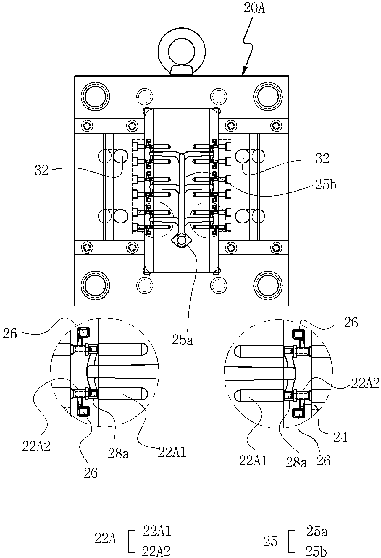
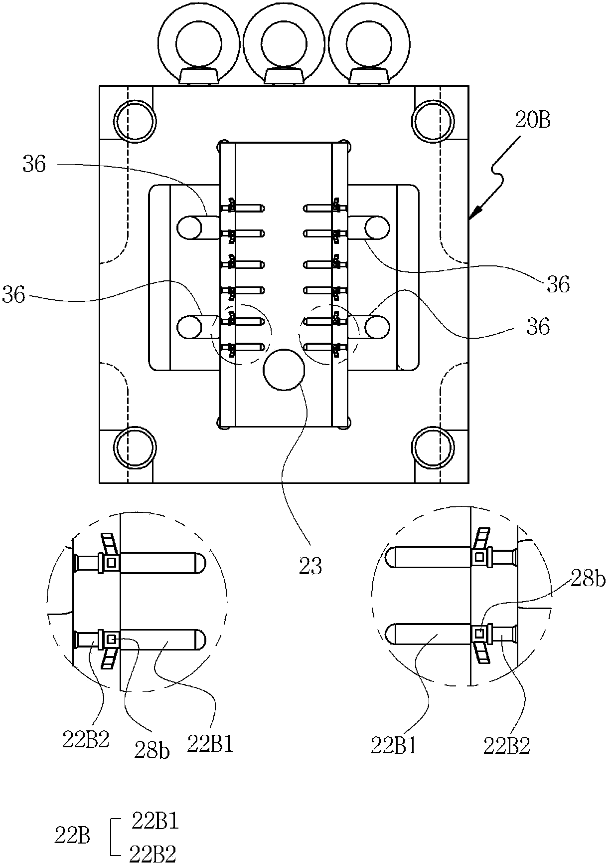
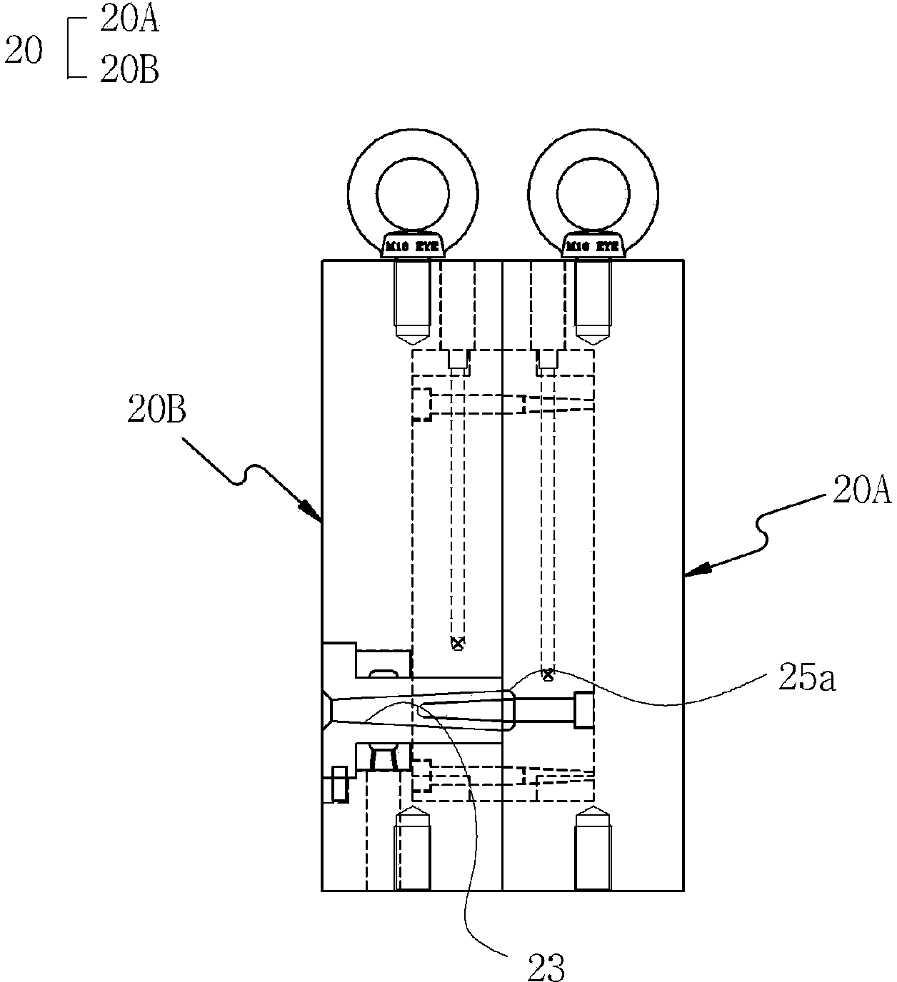
[0048] Referring to the accompanying drawings, in an embodiment of the present invention, in order to solve the above-mentioned problems, a method for manufacturing a power plug 10 is provided, which is used to manufacture a power plug 10 including a connecting portion 12 and an embedded portion 14, wherein the connecting portion 12 For inserting into the socket, the embedded part 14 is arranged at the rear of the above-mentioned connecting part 12 and built into the plug body. The manufacturing method of the power plug 10 includes the following steps: a plug forming step, and the inside has a shape corresponding to the shape of the above-mentioned plug 10. A forming die 20 of a plurality of pin cavities 22 injects molding material into such pin cavities 22 and forms the shape of the plug 10 through the above-mentioned pin cavities 22 of ...


PUM


Abstract

The invention provides a method for manufacturing a power plug and the power plug manufactured through the method. The method for manufacturing the power plug is used for manufacturing the power plug including a connecting portion and an embedded portion, the connecting portion is used for being inserted into a socket, and the embedded portion is arranged behind the connecting portion and is internally arranged on a plug body. The method for manufacturing the power plug is characterized by comprising the following steps that the plug is formed, a forming mould is manufactured, a plurality of plug cavities corresponding to the shape of the plug are formed in the forming mould, forming materials are injected into the plug cavities, and the shape of the plug is formed through the plug cavities of the forming mould; the forming materials which are injected into the plug cavities to form the plug are cured.

Description

technical field [0001] The present invention relates to a method for manufacturing a power plug and the power plug manufactured by the method. In more detail, it relates to manufacturing the plug by die-casting to improve production efficiency. By changing the material of the power plug, the manufacturing cost can be greatly reduced, and the softness can be increased. By improving the smooth fluidity of the casting solution inside the mold when die-casting the power plug, not only the formability of the plug is excellent, but also the high quality of the plug is guaranteed to prevent the wires connected to the plug from being twisted or broken. , so as to be able to obtain a new manufacturing method of the power plug and a power plug that can improve the quality of the plug and other preferred results. [0002] Furthermore, the present invention relates to the manufacture of a new power plug that uses a zinc alloy material instead of the currently used brass alloy for the powe...

Claims


Application Information

Patent Timeline
Patent Type & Authority Applications(China)
IPC IPC(8): H01R43/16H01R13/04
Inventor 金正国
Owner SINSEUNGTECH
Why Eureka
Try Eureka