
Fixed power distribution cabinet convenient to mount and maintain

A power distribution cabinet and installation room technology, applied in the field of fixed power distribution cabinets, can solve the problems of cluttered lines in the cable room, inconvenient heat dissipation, etc., and achieve the effect of saving the time for finding lines, arranging the lines neatly, and improving the efficiency of heat removal.

Active Publication Date: 2014-12-24
DAQING RUISID PETROLEUM MASCH MFG CO LTD
View PDF3 Cites 3 Cited by
  • Summary
  • Abstract
  • Description
  • Claims
  • Application Information

AI Technical Summary

Problems solved by technology

[0004]The purpose of the present invention is to solve the problem of messy lines in the cable room in the prior art, which is not convenient for heat dissipation and maintenance, and to provide a simple operation, good heat dissipation effect and convenient maintenance. Fixed distribution cabinet for easy installation and maintenance

Method used


Image

  • Fixed power distribution cabinet convenient to mount and maintain
  • Fixed power distribution cabinet convenient to mount and maintain
  • Fixed power distribution cabinet convenient to mount and maintain

Examples


Embodiment 1

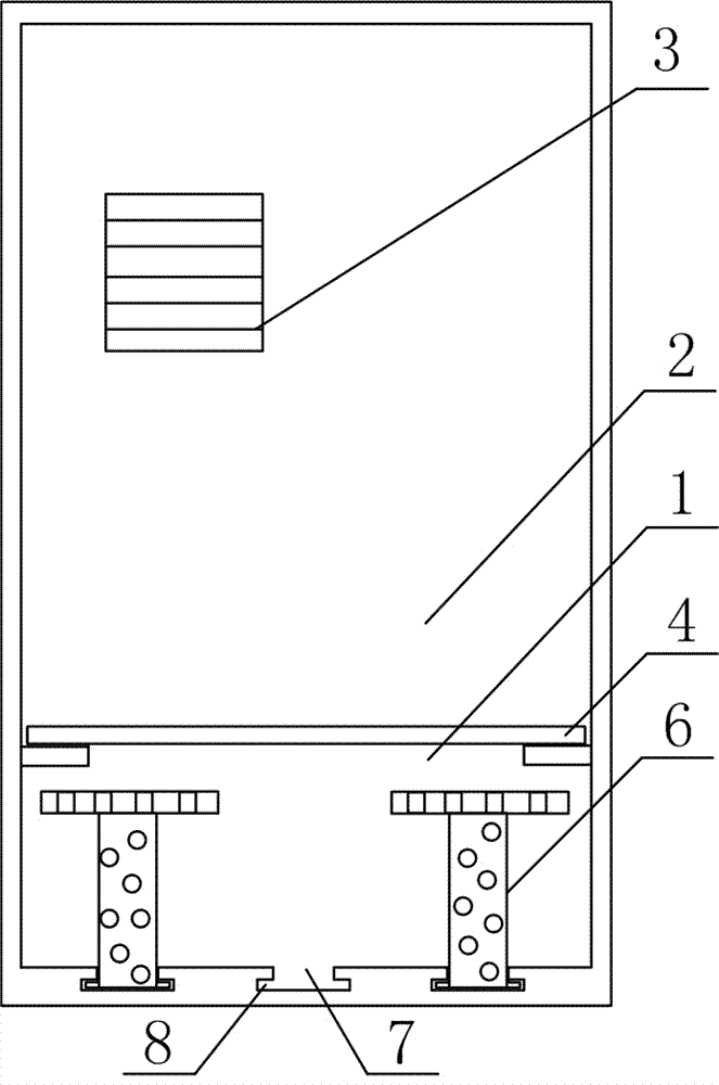
[0027] Fixed distribution cabinets for easy installation and maintenance, such as figure 1 As shown, it includes the cable room 1, the installation room 2, the vent 3, the detachable partition 4 and the hub 6. The specific arrangement of the above components and the connection relationship between them are as follows:

[0028] The cable room 1 is installed in the underground part, the installation room 2 is arranged above the cable room 1, and the cable room 1 and the installation room 2 are provided with air vents 3, such as figure 1 shown.

[0029] In order to facilitate maintenance and repair, a detachable partition 4 is arranged between the cable chamber 1 and the installation chamber 2, and the detachable partition 4 is provided with a line through hole 5, and the cable chamber 1 is also provided with a Hub 6, such as figure 1 shown.

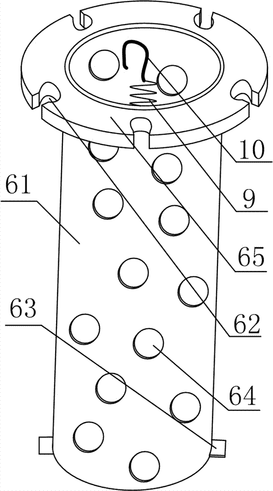
[0030] Such as image 3 As shown, the hub 6 is composed of a cylindrical barrel 61, a wire slot 62 arranged at the upper end of the...

Embodiment 2

[0034] The difference between this embodiment and Embodiment 1 is that the structure of the fixing member 63 is different. The specific structure of the fixing member 63 in this embodiment is set as follows:

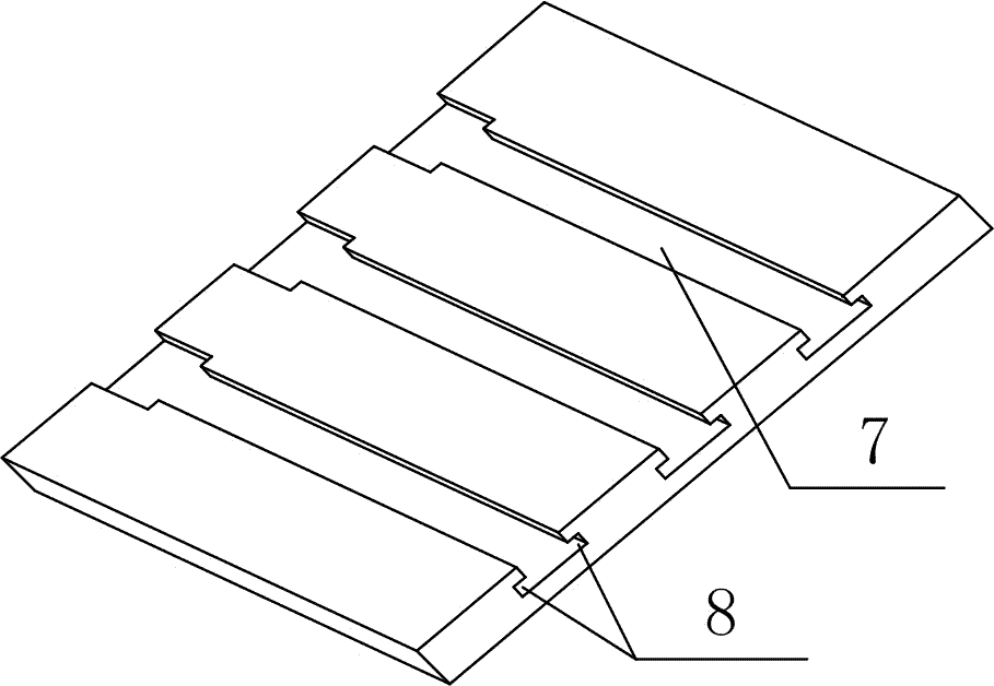
[0035] The fixing piece 63 is a fixing sheet arranged on opposite sides of the lower end of the cylinder body 61 , the bottom surface of the cable chamber 1 is provided with a groove body 7 having the same width as the diameter of the cylinder body 61 , and is arranged on both sides of the groove body 7 Card slot 8 matching the fixed piece, such as figure 2 shown.

[0036] Because the hub 6 is fixed on the groove body of the cable chamber 1 by the fixing piece thereon, it is all very convenient to take out and install. Therefore, before and after wiring, this setting method is very convenient for maintenance and repair of the line.

Embodiment 3

[0038] The difference between this embodiment and Embodiment 1 and Embodiment 2 is that: the structure at the position of the clamping groove 62 is optimized, and the specific settings are as follows:

[0039] The upper end of the cylinder body 61 is provided with an annular connecting body 65, and the clamping grooves 62 are evenly distributed around the annular connecting body 65, as image 3 shown.

[0040] A hook 10 connected to the cylinder 61 through a spring 9 is also provided at the hollow position.

[0041] After all the redundant cables are wound on the cylinder body 61, one end extending to the installation chamber 2 is clipped into the cable clamping groove 62, and then the hook 10 is hooked to the cable, since the hook 10 is connected by the spring 9 To the hollow position of the cylinder body 61, the effect of the spring 9 can effectively tighten the cable between the wire clamping groove 62 and the hook 10, preventing the cable from coming out of the wire clamp...


PUM


Abstract

The invention discloses a fixed power distribution cabinet convenient to mount and maintain and mainly solves the problem of inconvenience in heat radiation and maintenance due to messy lines in cable chambers in the prior art. The fixed power distribution cabinet convenient comprises an underground cable chamber (1), a mounting chamber (2) and vent holes (3), wherein the mounting chamber (2) is arranged above the underground cable chamber (1), and the vent holes (3) are arranged between the cable chamber (1) and the mounting chamber (2). The fixed power distribution cabinet is characterized in that a detachable partition plate (4) is arranged between the cable chamber (1) and the mounting chamber (2) and provided with line through holes (5), wire collectors (6) are arranged in the cable chamber (1), each wire collector (6) comprises a cylindrical barrel (61), wire clamping grooves (62), fixing parts (63) and air vents (64), the upper ends of the cylindrical barrels (61) are provided with the wire clamping grooves (62), the fixing parts (63) are arranged at the lower ends of the cylindrical barrels (61), and the cylindrical barrels (61) are provided with the air vents (64). The fixed power distribution cabinet has the advantages of simplicity in operation, effectiveness in heat radiation, convenience in maintenance and the like.

Description

technical field [0001] The invention relates to a power distribution cabinet, in particular to a fixed power distribution cabinet which is convenient for installation and maintenance. Background technique [0002] The power distribution cabinet is a kind of electrical equipment. The main function of the power distribution cabinet is to open and close, control and protect electrical equipment during the process of power generation, transmission, distribution and power conversion in the power system. The components in the power distribution cabinet are mainly composed of circuit breakers, isolating switches, load switches, operating mechanisms, transformers and various protection devices. There are many classification methods for power distribution cabinets. For example, according to the installation method of circuit breakers, it can be divided into removable power distribution cabinets and fixed power distribution cabinets; or according to different cabinet structures, it ca...

Claims


Application Information

Patent Timeline
Patent Type & Authority Applications(China)
IPC IPC(8): H02B1/20
Inventor 李胜峰
Owner DAQING RUISID PETROLEUM MASCH MFG CO LTD
Learn More