Cable positioning element and charging gun using same

A technology for positioning components and charging guns, applied in the direction of electrical components, battery circuit devices, current collectors, etc., can solve problems that affect the assembly of cables, and achieve the effect of avoiding axial offset

Inactive Publication Date: 2014-12-24
KS TERMINALS INC
View PDF1 Cites 6 Cited by
  • Summary
  • Abstract
  • Description
  • Claims
  • Application Information

AI Technical Summary

Problems solved by technology

In addition, in order to make the user's operation more convenient, the gun body and the grip part of the charging gun will be bent at a certain angle. Therefore, in order to fix the wires inside the gun body and the grip part, workers on the assembly line need to use a flexible The plastic is set on the...

Method used


Image

  • Cable positioning element and charging gun using same
  • Cable positioning element and charging gun using same
  • Cable positioning element and charging gun using same

Examples


Embodiment Construction

[0018] The structure and effect of the present invention will be described in detail by citing the following embodiments in conjunction with the accompanying drawings.

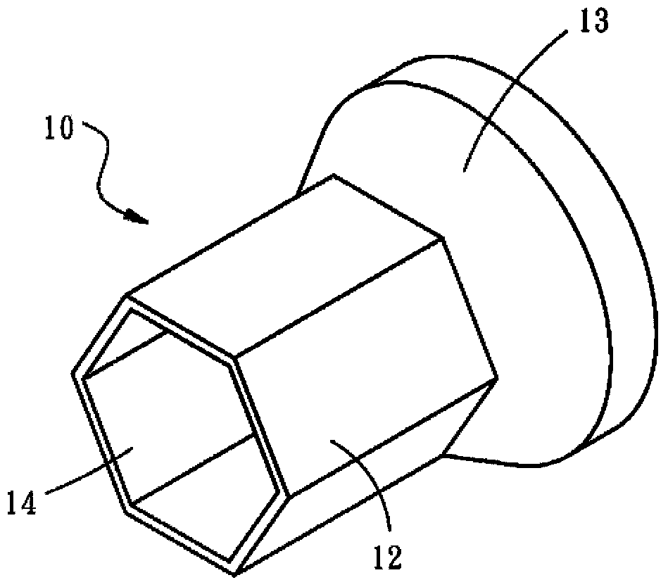
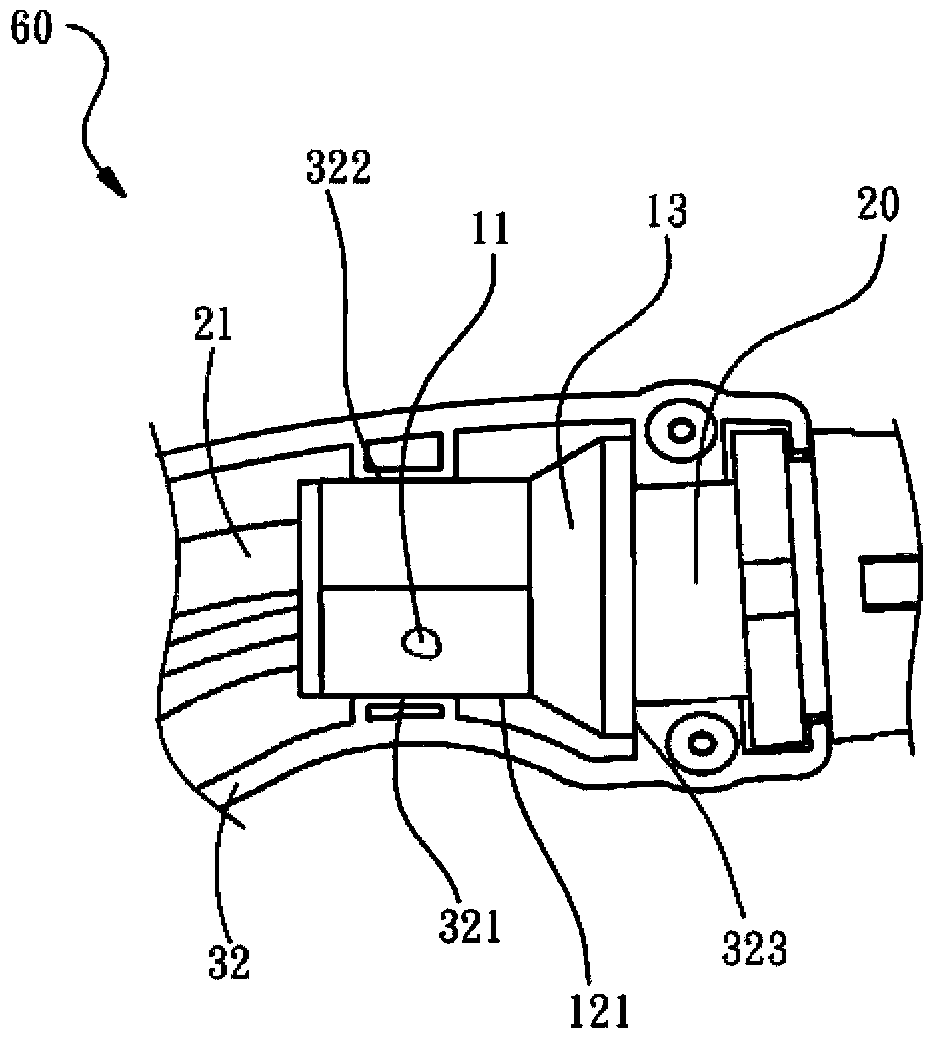
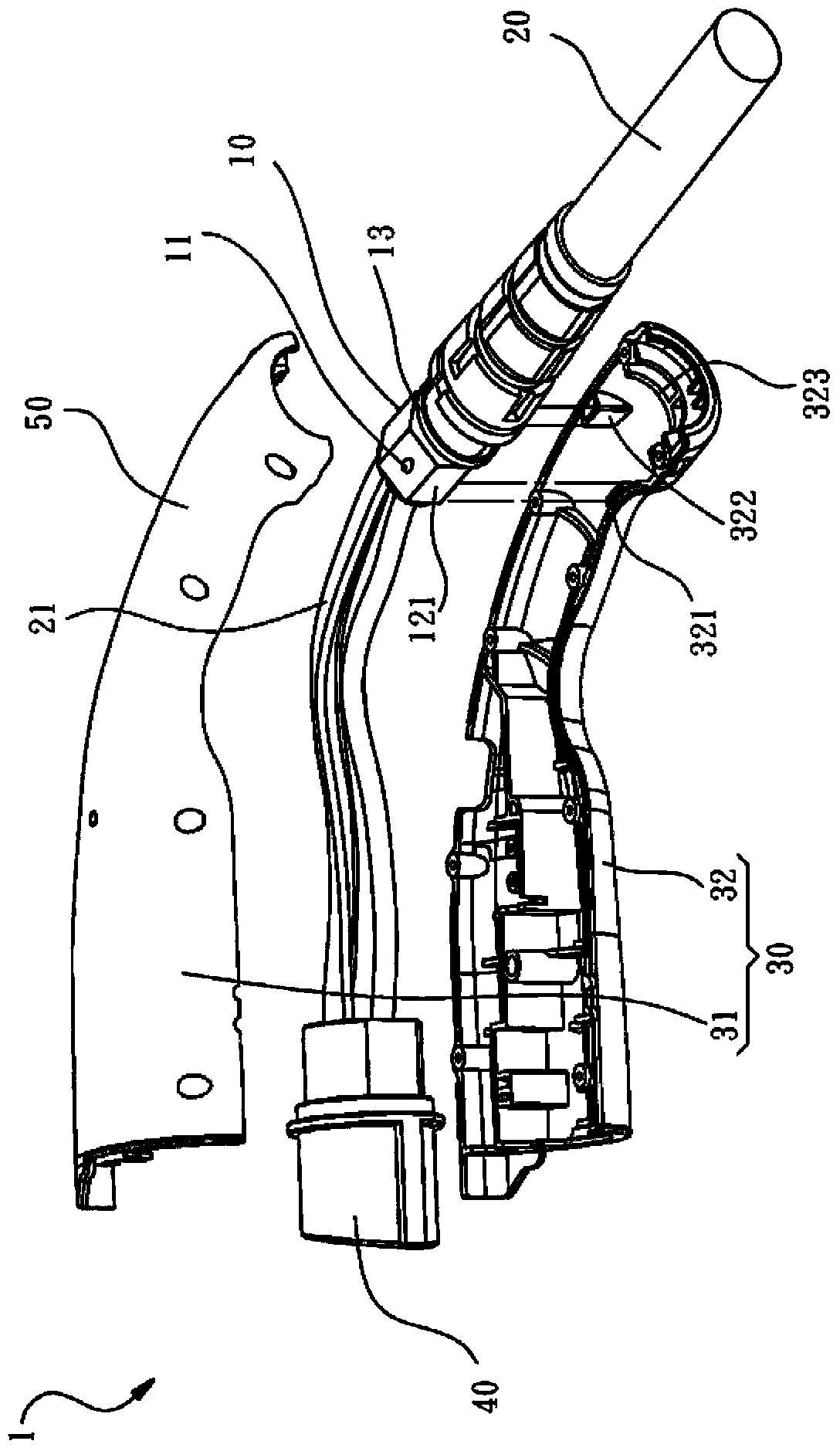
[0019] Such as Figure 1 to Figure 4 As shown, the preferred embodiment of the present invention provides a charging gun 1, which has a gun body 30, a grip portion 50 disposed on the gun body 30, and a mounting seat 60 integrally formed inside the grip portion 50. , a cable 20 passes through the grip portion 50, and a cable positioning element 10 is also provided inside the mounting base 60 for installing and positioning the cable 20. The cable positioning element 10 includes a cylinder 12 with a polygonal cross section, and the inner A hollow passage 14 is provided for the cable 20 to pass through. The cylinder 12 can be subjected to force to produce inelastic deformation to compress the cable 20 . The detailed component relationship description of this embodiment is as follows:

[0020] In this embodiment,...


PUM


Abstract

The invention relates to a cable positioning element and a charging gun using the cable positioning element. The cable positioning element is suitable for mounting a cable in a mounting base. The cable positioning element includes a column of which the cross section is polygonal, and a hollow channel is formed in the column and allows penetration of the cable. The column can be stressed to produce inelastic deformation to press against the cable, and at least one side face of the column can abut against one inner wall face of the mounting base. Accordingly, the situation that due to the distortion and rotation of the cable, the cable positioning element and wires in the cable positioning element rotate can be avoided, and the assembly efficiency of the cable is improved.

Description

technical field [0001] The invention relates to a positioning element of a cable, in particular to a positioning element suitable for the interior of a charging gun and used to fix the cable, which can prevent the charging gun from being caused by the twisting and rotation of the cable outside the charging gun when the charging gun moves. The rotation of the internal cable can also improve the assembly efficiency of the cable. Background technique [0002] Cables are used to transmit electrical signals and are the basic components of many machines and are well known. However, for the stability of the transmission signal, U.S. Patent No. 4,394,531 discloses a protection device for preventing transmission line vibration. This structure and the frictional force of the abutment of the transmission line fix the transmission line and reduce the impact of the transmission line on the vibration of the environment. Although this protection device can reduce the vibration caused by ...

Claims


Application Information

Patent Timeline
IPC IPC(8): H02G3/02H02J7/00
Inventor 林昌宜
Owner KS TERMINALS INC
Why Eureka
Try Eureka