
Motor and motor shaft thereof

A motor shaft and spindle technology, applied in the direction of engine, electromechanical device, electrical components, etc., can solve the problems of low structural strength, broken and damaged motor shaft, shortened shaft service life, etc., to improve connection stability, ensure normal operation, improve The effect of structural strength

Inactive Publication Date: 2021-04-06
陈艳红
View PDF1 Cites 1 Cited by
  • Summary
  • Abstract
  • Description
  • Claims
  • Application Information

AI Technical Summary

Problems solved by technology

[0004] In the process of realizing the present invention, the inventor found that at least the following problems in the prior art have not been solved: the prior art solves the problem that the motor shaft is easily subjected to the axial impact force of the load and causes axial misalignment, but the prior art shaft end The structural strength of the connection position with the main shaft is low. For the permanent magnet motor with high speed, it is easy to break the motor shaft and damage the equipment, and at the same time, the connection position between the shaft end and the main shaft is poorly sealed. During the process, there are a lot of dust and impurities in the ambient air, which will cause the shaft to wear and shorten the service life of the shaft if it enters the connection position between the shaft end and the main shaft.

Method used


Image

  • Motor and motor shaft thereof
  • Motor and motor shaft thereof
  • Motor and motor shaft thereof

Examples


Embodiment Construction

[0032] The following will clearly and completely describe the technical solutions in the embodiments of the present invention with reference to the accompanying drawings in the embodiments of the present invention. Obviously, the described embodiments are only some, not all, embodiments of the present invention. Based on the embodiments of the present invention, all other embodiments obtained by persons of ordinary skill in the art without making creative efforts belong to the protection scope of the present invention.

[0033] In describing the present invention, it is to be understood that the terms "center", "longitudinal", "transverse", "length", "width", "thickness", "upper", "lower", "front", " Back", "Left", "Right", "Straight", "Horizontal", "Top", "Bottom", "Inner", "Outer", "Clockwise", "Counterclockwise", etc. or The positional relationship is based on the orientation or positional relationship shown in the drawings, which are only for the convenience of describing ...


PUM


Abstract

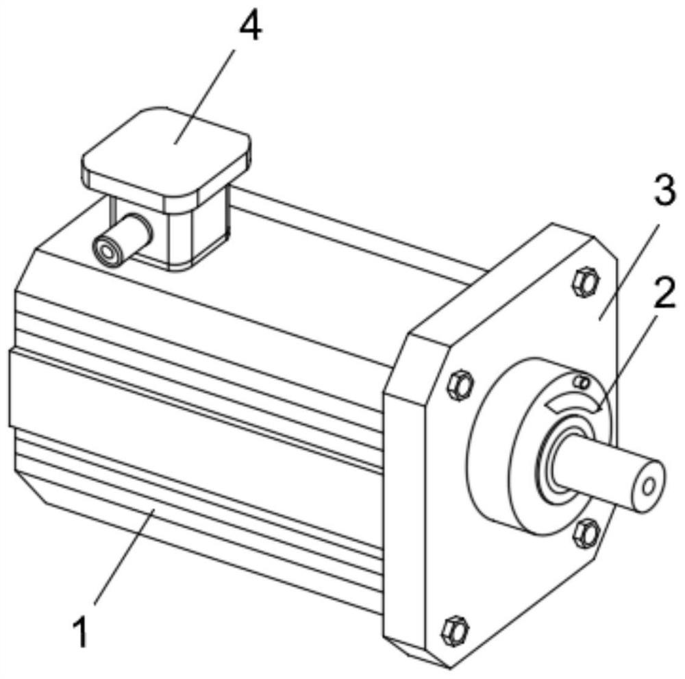
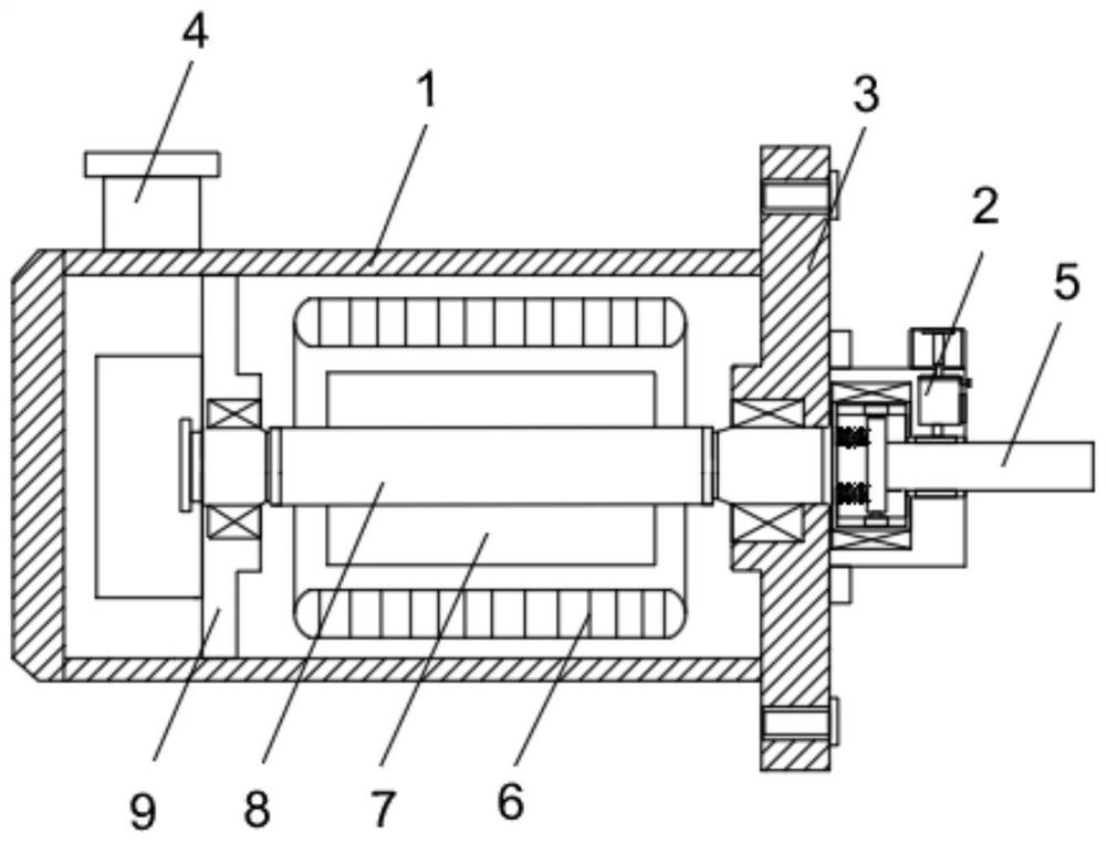
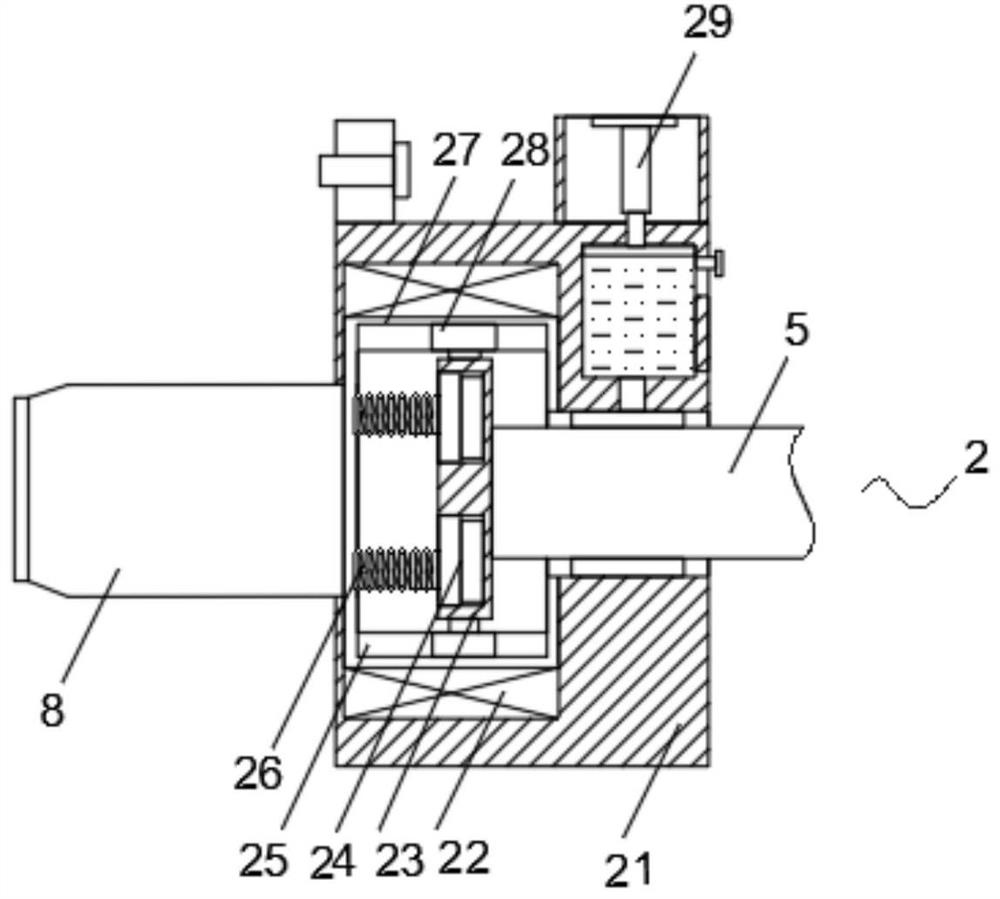
The invention discloses a motor and a motor shaft thereof. The motor comprises a housing which is provided with a working mechanism. An axial stabilizing mechanism is fixedly installed in the middle of the side surface of one end of the shell. The working mechanism comprises a mounting plate, a photoelectric encoder, a shaft end, an armature coil, a permanent magnet, a main shaft and a fixed plate. The mounting plate is fixedly mounted on the side surface of one end of the shell. According to the motor and the motor shaft thereof, by arranging the axial stabilizing mechanism, the axial impact force of a load is buffered, axial dislocation is avoided, meanwhile, a connecting shaft can be limited through a fixing shell and a ball bearing, then the structural strength of the connecting position of the shaft end and the main shaft is improved, and normal operation of the motor is guaranteed; and meanwhile, a protection mechanism is arranged, dust and impurities in the external environment can be prevented from entering the connecting position of the shaft end and the main shaft to cause abrasion of the shaft, and the service life of the shaft end is prolonged.

Description

technical field [0001] The invention relates to the technical field of motors, in particular to a motor and a motor shaft thereof. Background technique [0002] The permanent magnet synchronous motor provides excitation with permanent magnets, which makes the structure of the motor relatively simple, reduces the cost of processing and assembly, and saves the collector ring and brush that are prone to problems, which improves the reliability of the motor operation; and because no excitation is required current, without field losses, increasing the efficiency and power density of the motor. [0003] The existing patent (notification number: CN211231247U) is a connected motor shaft, including a main shaft, a groove is opened on the right side of the main shaft, and the inner side wall of the groove is provided with four limit positions located inside the main shaft. The groove, the left side wall of the inner cavity of the groove is fixedly connected with the limiting spring, ...

Claims


Application Information

Patent Timeline
Patent Type & Authority Applications(China)
IPC IPC(8): F16F15/12F16F15/123F16N11/08F16N29/00F16N39/04H02K11/22
CPCF16F15/1201F16F15/1232F16F2238/026F16N11/08F16N29/00F16N39/04F16N2210/18H02K11/22
Inventor 陈艳红张飞
Owner 陈艳红
Learn More