A pipe fitting angle welding equipment

A technology of welding equipment and pipe fittings, which is applied in the field of pipe fitting angle welding equipment, can solve the problems affecting the quality of workpieces, the axial deviation of pipe fittings, and the difficulty of moving pipe fittings, so as to achieve the effect of improving welding quality and avoiding axial deviation

Active Publication Date: 2018-08-07
WUHU JINGFENG GARDEN MACHINERY TECH
View PDF8 Cites 1 Cited by
  • Summary
  • Abstract
  • Description
  • Claims
  • Application Information

AI Technical Summary

Problems solved by technology

[0002] Most of the existing pipe fittings are welded by manual welding, which is labor-intensive and inefficient, and when it is necessary to ensure a certain angle between two welded pipe fittings, workers need to continuously move the position of the pipe fittings to form a certain welding angle. However, for some large-diameter workpieces, it is quite difficult to move the pipe fittings, and often requires the cooperation of multiple people to move, which is time-consuming and labor-intensive
In addition, when the workpiece is working during the welding process, it is necessary to manually rotate the workpiece, and manual rotation can easily cause the axial deviation of the pipe fittings and affect the quality of the workpiece

Method used


Image

  • A pipe fitting angle welding equipment
  • A pipe fitting angle welding equipment

Examples


Embodiment Construction

[0039] Hereinafter, the technical solution of the present invention will be described in detail through specific embodiments.

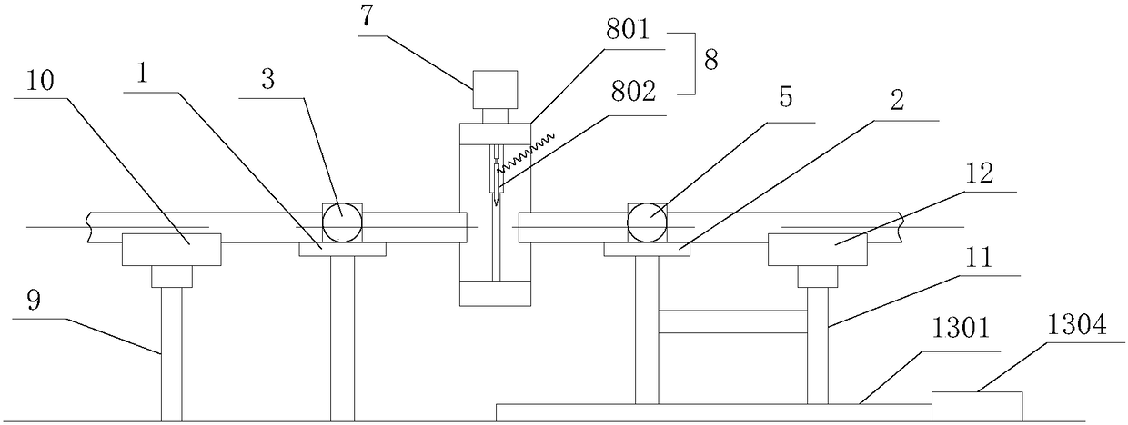
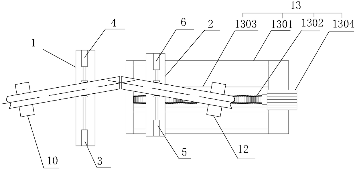
[0040] Such as Figure 1-2 As shown, figure 1 It is a schematic structural diagram of a pipe angle welding equipment proposed by the present invention; figure 2 It is a top view of a pipe angle welding equipment proposed by the present invention.

[0041] Reference Figure 1-2 , An angle welding equipment for pipe fittings proposed in an embodiment of the present invention includes: a first working table 1, a second working table 2, a first pushing device 3, a second pushing device 4, a third pushing device 5, and a Four pusher device 6, slide rail 7, welding device 8 and driving device, of which:

[0042] The first workbench 1 and the second workbench 2 are on the same straight line. The first workbench 1 is far away from the second workbench 2 with a first upright 9 which is rotatably mounted on the top end of the first upright 9 The pallet 10, the fir...


PUM


Abstract

The invention discloses a pipe angle welding device which comprises a first workbench, a second workbench, a first push device, a second push device, a third push device, a fourth push device, a slide rail, a welding unit and a drive unit. The first workbench and the second workbench are both used for supporting pipes; the first push device, the second push device, the third push device and the fourth push device are all used for pushing the pipes to skew; the drive unit and the slide rail are mutually matched for driving the welding unit to move; and a drive mechanism in the welding unit is matched with a ring sleeve for enabling a welding gun to rotate by 360 degrees. The pipe angle welding device achieves automatic adjustment of pipe welding angles, and rotation of the pipes in the welding process is not needed.

Description

Technical field [0001] The invention relates to the technical field of pipe fitting welding, in particular to a pipe fitting angle welding equipment. Background technique [0002] Most of the existing pipe fittings are welded manually, which is labor-intensive and low in efficiency. When it is necessary to ensure that there is a certain angle between two welded pipe fittings, workers need to constantly move the position of the pipe fittings to form a certain weld. Angle, however, for some large-caliber workpieces, it is quite difficult to move the pipe fittings. It often requires the cooperation of many people to move, which is time-consuming and labor-intensive. In addition, the workpiece needs to be manually rotated during the welding process, and manual rotation can easily cause the axial deviation of the pipe to affect the quality of the workpiece. Summary of the invention [0003] Based on the technical problems existing in the above-mentioned background technology, the pres...

Claims


Application Information

Patent Timeline
Patent Type & Authority Patents(China)
IPC IPC(8): B23K37/053B23K37/02
CPCB23K37/0229B23K37/0461B23K37/0533B23K2101/06
Inventor 王泉福马国章周德忠张立群
Owner WUHU JINGFENG GARDEN MACHINERY TECH
Why Eureka
Try Eureka