Current conduction nozzle

The technology of contact tip and body is applied in the field of contact tip, which can solve the problems of difficult processing of the inner hole of the contact tip and low matching accuracy of the inner hole of the contact tip, and achieve the effects of simple structure, easy processing and cost saving.

Pending Publication Date: 2018-08-24
NAT INST CORP OF ADDITIVE MFG XIAN
View PDF6 Cites 1 Cited by
  • Summary
  • Abstract
  • Description
  • Claims
  • Application Information

AI Technical Summary

Problems solved by technology

[0003] In order to overcome the problems of difficulty in processing the inner hole of the existing contact tip and the low matching accuracy between the diameter of the inner hole of the contact tip and the diameter of the wire, the present invention provides a contact tip

Method used


Image

  • Current conduction nozzle
  • Current conduction nozzle
  • Current conduction nozzle

Examples


Embodiment Construction

[0026] The present invention will be described in detail below in conjunction with the accompanying drawings.

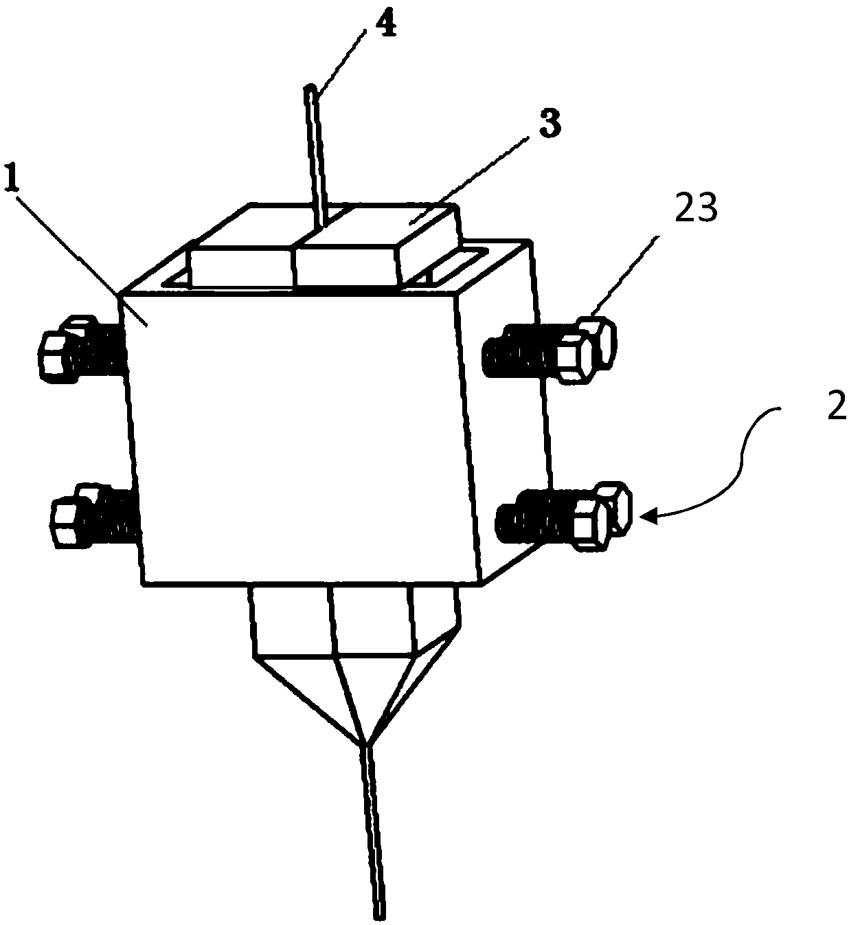
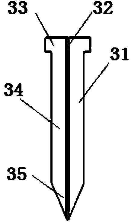
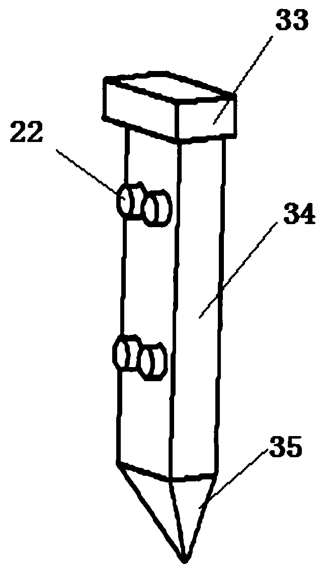
[0027] like Figure 1-5 As shown, the contact tip of the present invention includes a contact tip body 3, a housing 1 and a spring adjustment device 2; the housing 1 is provided with a contact tip body mounting hole 11, and the wall of the housing 1 is provided with two sets of threaded mounting holes 12, The two sets of threaded mounting holes 12 are located at two different heights in the axial direction of the housing 1 . Each set of threaded holes includes four threaded holes, and the four threaded holes are symmetrically arranged on two opposite side walls of the housing 1 . The spring adjusting device 2 includes a spring 21 corresponding to the threaded mounting hole 12, a boss 22 and a bolt; the contact tip body 3 is composed of two mating bodies 31, and the mating surfaces of the two mating bodies 31 are respectively provided with a half groove. Two half gr...


PUM


Abstract

The invention relates to a current conduction nozzle which comprises a current conduction nozzle body, a shell and a spring adjusting device. The shell is provided with a current conduction nozzle body installing hole, and a plurality of threaded installing holes are formed in the shell wall and are symmetrically arranged around the current conduction nozzle body installing hole; the spring adjusting device comprises springs, bosses and threaded connecting pieces which correspond to the threaded installing holes in a one-to-one manner; the current conduction nozzle body is formed by two matching bodies, the matching faces of the two matching bodies are each provided with a semi-groove, and the two semi-grooves are combined to form a wire penetrating hole; each matching body sequentially comprises an axial positioning section, a matching section and an extending-out section from the wire inlet end and the wire outlet end; the current conduction nozzle body and the shell are installed ina matched manner, the axial positioning sections are located outside the shell, the matching sections are located inside the shell, and the extending-out sections extend out of the shell. The currentconduction nozzle solves the problem that an existing current conduction nozzle inner hole is difficult to machine, and the matching precision of the diameter of the current conduction nozzle inner hole and the wire diameter is low; and the current conduction nozzle has the beneficial effects that machining is easy, the matching accuracy is high, adjustment is facilitated, efficiency is high, andthe service life is long.

Description

technical field [0001] The invention relates to a conductive tip. Background technique [0002] The inner hole of the contact tip is a slender hole, which is relatively difficult to process, and it is difficult to meet the process requirements of the contact tip. Generally, in order to make the welding wire pass through the inner hole of the contact tip smoothly, the diameter of the inner hole of the contact tip must be processed larger than the diameter of the welding wire, so that the following problems arise: First, irregular shaking occurs when the welding wire is drawn out, especially After the wear of the inner hole becomes larger, the swaying range is greater. Once the inner hole is worn or out of round, it will directly affect the welding quality; second, there is no self-compensation, and the machine-made welding wire is in loose contact with the inner hole of the contact tip. It is a pity that the new contact tip will be burned when it is first arced, and the wast...

Claims


Application Information

Patent Timeline
Patent Type & Authority Applications(China)
IPC IPC(8): B23K9/26
CPCB23K9/26
Inventor 王万军闫雪萍王强李波波翼千瑜施建旭任晓飞
Owner NAT INST CORP OF ADDITIVE MFG XIAN
Why Eureka
Try Eureka