A device and method for testing electric equipment

A kind of electric equipment, square wave technology, used in measuring devices, output power conversion devices, measuring electricity and other directions

Active Publication Date: 2017-06-16
POWER SUZHOU
View PDF2 Cites 0 Cited by
  • Summary
  • Abstract
  • Description
  • Claims
  • Application Information

AI Technical Summary

Problems solved by technology

[0005] The technical problem to be solved by the present invention is to overcome the defects of devices and methods for testing electric equipment in the prior art

Method used


Image

  • A device and method for testing electric equipment
  • A device and method for testing electric equipment
  • A device and method for testing electric equipment

Examples


Embodiment 1

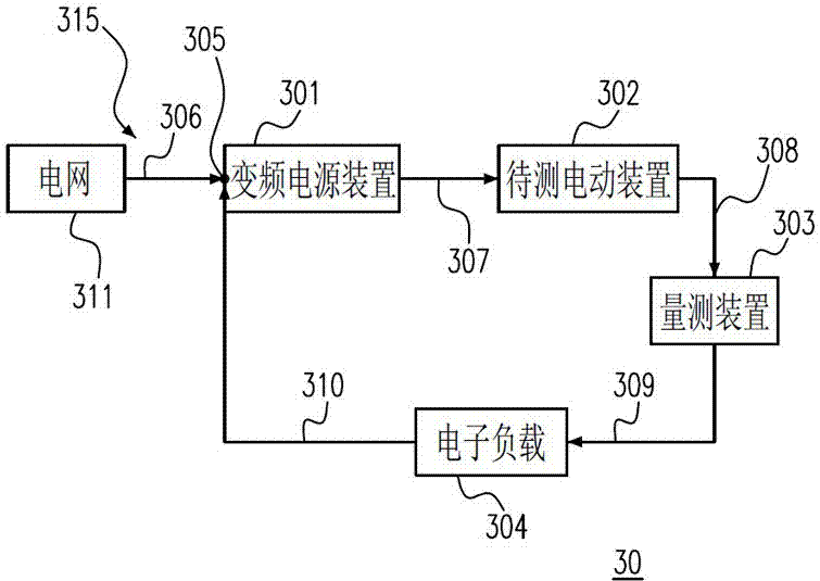
[0108] Embodiment one: see image 3 , which is a schematic diagram of a device 30 for testing electric equipment in Embodiment 1 of the present invention. The device 30 includes a variable frequency power supply device 301 , an electric device to be tested 302 , a measuring device 303 , and an electronic load 304 . see Figure 4 , which is a schematic diagram of the reference AC voltage / current and the feedback AC voltage / current. Please also see image 3 and Figure 4 The variable frequency power supply device 301 has an input terminal 305, the input terminal 305 receives a reference AC voltage 306, and the variable frequency power supply device 301 outputs a first AC voltage 307 with an adjustable parameter in response to the reference AC voltage 306. The electric device under test 302 generates a mechanical kinetic energy 308 in response to the first AC voltage 307 . The measuring device 303 converts the mechanical kinetic energy 308 into a second AC voltage 309 and me...

Embodiment 2

[0124] Example 2: Please refer to Figure 10 , which is a schematic diagram of a device 40 for testing electric equipment according to a second preferred embodiment of the present invention. The device 40 includes the variable frequency power supply device 301 , the electrical equipment under test 302 , the measuring device 303 , and a rectifying unit 3020 . The variable frequency power supply device 301 includes a rectification unit 3011 and an inverter 3013 . The variable frequency power supply device 301 has an input terminal 305 , the input terminal 305 receives a power 401 , and the rectification unit 3011 responds to the reference AC voltage 306 of the power 401 to output a DC voltage VDC1 . The converter 3013 includes a converter unit 3014, and outputs a first AC voltage 307 with an adjustable parameter in response to the DC voltage VDC1. The electric device under test 302 generates mechanical kinetic energy 308 in response to the first AC voltage 307 . The measuring...

Embodiment 3

[0127] Example 3: Please refer to Figure 11 , which is a schematic diagram of a power saving device 50 for testing an energy conversion device in Embodiment 3 of the present invention. The power saving device 50 includes a variable frequency power supply device 501 , the energy conversion device 502 , and an electronic load 503 . The variable frequency power supply device 501 outputs a second power 505 in response to a first power 504 . The energy conversion device 502 generates kinetic energy in response to the second electric power 505 , converts the kinetic energy into a third electric power 506 , and measures the kinetic energy by the third electric power 506 . The electronic load 503 generates a fourth power 507 in response to the third power 506 , wherein the fourth power 507 is mixed with the first power 504 to recover the first power 504 .

[0128] In the third embodiment of the present invention, the first electric power 504 is sent from the grid 508, and the energ...


PUM


Abstract

The invention relates to a device for testing electric equipment, which includes a variable frequency power supply device, an electric equipment to be tested, a measuring device, and an electronic load. The variable frequency power supply device has an input end, and the input terminal receives a reference AC voltage, and the variable frequency power supply device outputs a first AC voltage with an adjustable frequency in response to the reference AC voltage. The electric device under test generates mechanical kinetic energy in response to the first AC voltage. The measuring device converts the mechanical kinetic energy into a second AC voltage, and measures the mechanical kinetic energy through the second AC voltage. The electronic load provides a feedback AC voltage to the input end in response to the second AC voltage. The invention can improve the test accuracy and output efficiency of the electric equipment, and also has the power feedback function, which can efficiently feed back most of the power required in the testing and aging experiments to the testing device, and recycle it to achieve energy saving effect, and Can save a lot of testing costs.

Description

technical field [0001] The present invention relates to a device and method for testing electric equipment, in particular to a device and method for testing electric equipment by utilizing energy cycle recovery. Background technique [0002] With the development of industrial economy, motors used as electric equipment for fans, water pumps, compressors, machine tools, printing, papermaking, textiles, steel rolling equipment, factory production lines, urban transportation, and transportation vehicles have been widely used in various industries. Applications. According to authoritative statistics, about 56% of the world's electric energy is consumed by motor power devices every year. [0003] See figure 1 , which is a schematic diagram of a conventional electric device testing device 10 . The electric device testing device 10 includes a drive motor 101 , a generator 102 , a motor to be tested 103 , a dynamometer 104 , and a load box 105 . The drive motor 101 receives a com...

Claims


Application Information

Patent Timeline
Patent Type & Authority Patents(China)
IPC IPC(8): H02M5/458G01R31/00G01R31/34
Inventor 施镇宇
Owner POWER SUZHOU
Why Eureka
Try Eureka