Motor phase current prediction and diagnosis method

A diagnostic method and phase current technology, applied in the control of generators, motor generator control, electronic commutation motor control, etc., can solve the problems that affect the accuracy and effectiveness of angle estimation, reduce the accuracy and reliability of motor control, and achieve Protect stability and smoothness of mechanical system, improve reliability and save cost

Active Publication Date: 2014-12-24
CHINA FIRST AUTOMOBILE
View PDF7 Cites 17 Cited by
  • Summary
  • Abstract
  • Description
  • Claims
  • Application Information

AI Technical Summary

Problems solved by technology

One disadvantage of this motor control device is that the motor body parameters used in the estimation formula, such as the permanent magnet synchronous motor winding resistance and winding inductance, are physical quantities that change continuously with temperature and motor phase current. This method does not mention the above Effective compensation of parameters will affect the accuracy and effectiveness of angle estimation, which will reduce the accuracy and reliability of motor control

Method used


Image

  • Motor phase current prediction and diagnosis method
  • Motor phase current prediction and diagnosis method
  • Motor phase current prediction and diagnosis method

Examples


Embodiment 1

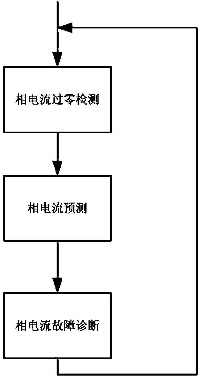
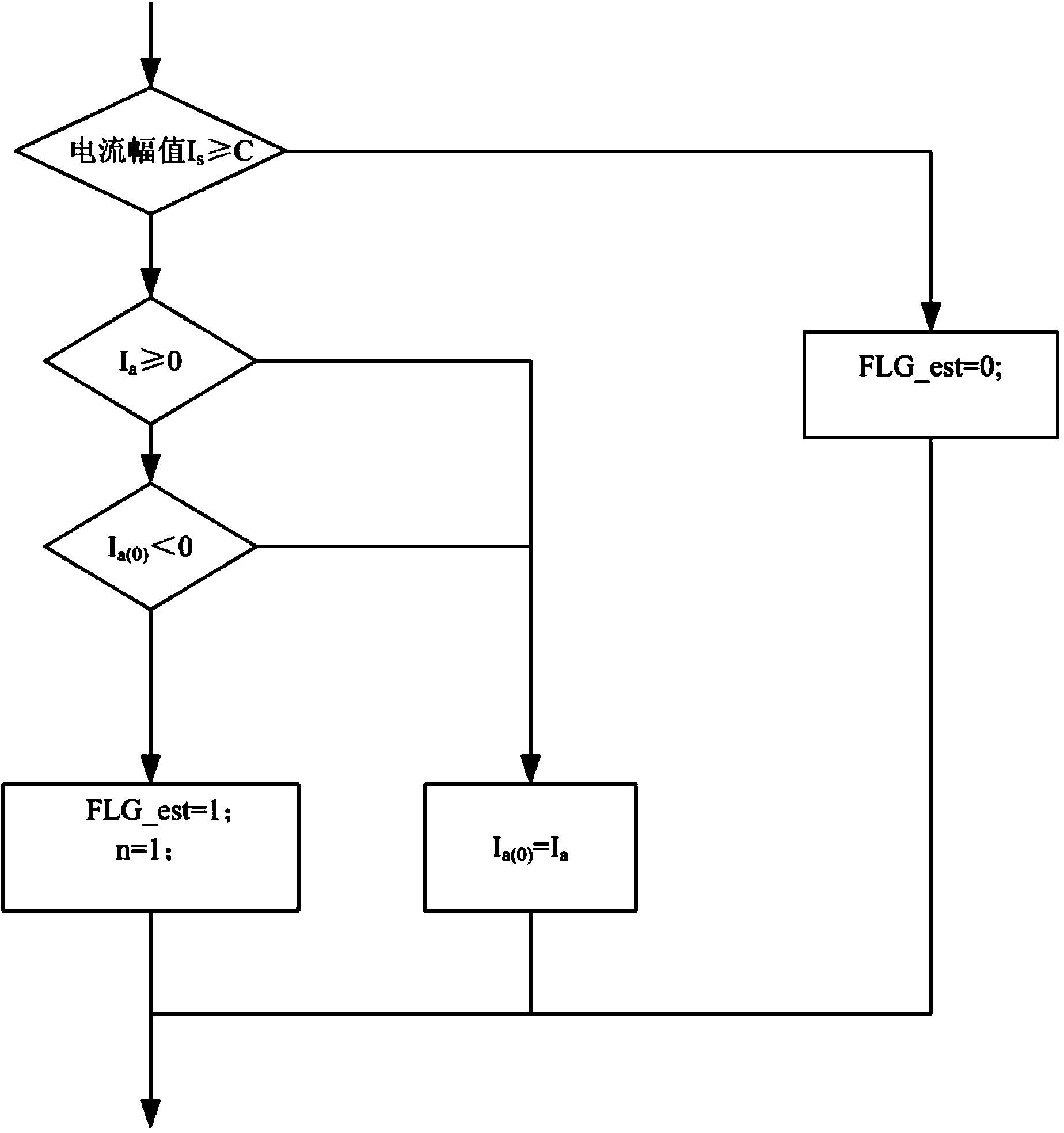
[0039] like figure 2 As shown, the motor phase current prediction and diagnosis method of the present invention includes three parts: phase current zero-cross detection, phase current prediction and phase current fault diagnosis. The first part of phase current zero-cross detection includes the following steps:

[0040] Step 1: Determine whether the current amplitude is greater than the set C value, if so, go to Step 3, otherwise, go to Step 2;

[0041] Step 2: Set the prediction completion flag FLG_est to 0, and then end the program;

[0042] Step 3: Determine the current sampling value I of phase A at this sampling time a Whether it is greater than or equal to zero, if so, go to step 4, otherwise, go to step 5;

[0043] Step 4: Determine the A-phase current sampling value I at the last sampling time a(0) Whether it is less than zero, if so, go to step six, otherwise go to step five;

[0044] Step 5: Let I a(0) =I a , then end the program;

[0045] Step 6: Set the pre...

Embodiment 2

[0059] like figure 2 As shown, the motor phase current prediction and diagnosis method of the present invention includes three parts: phase current zero-cross detection, phase current prediction and phase current fault diagnosis. The first part of phase current zero-cross detection includes the following steps:

[0060] Step 1: Determine whether the current amplitude is greater than the set C value, if so, go to Step 3, otherwise, go to Step 2;

[0061] Step 2: Set the prediction completion flag FLG_est to 0, and then end the program;

[0062] Step 3: Determine the B-phase current sampling value I at the current sampling time b Whether it is greater than or equal to zero, if so, go to step 4, otherwise, go to step 5;

[0063] Step 4: Determine the B-phase current sampling value I at the last sampling time b(0) Whether it is less than zero, if so, go to step six, otherwise go to step five;

[0064] Step 5: Let I b(0) =I b , then end the program;

[0065] Step 6: Set the...

Embodiment 3

[0078] like figure 2As shown, the motor phase current prediction and diagnosis method of the present invention includes three parts: phase current zero-cross detection, phase current prediction and phase current fault diagnosis. The first part of phase current zero-cross detection includes the following steps:

[0079] Step 1: Determine whether the current amplitude is greater than the set C value, if so, go to Step 3, otherwise, go to Step 2;

[0080] Step 2: Set the prediction completion flag FLG_est to 0, and then end the program;

[0081] Step 3: Determine the C-phase current sampling value I at the sampling moment c Whether it is greater than or equal to zero, if so, go to step 4, otherwise, go to step 5;

[0082] Step 4: Determine the C-phase current sampling value I at the last sampling time c(0) Whether it is less than zero, if so, go to step six, otherwise go to step five;

[0083] Step 5: Let I c(0) =I c , then end the program;

[0084] Step 6: Set the predic...


PUM


Abstract

The invention relates to a motor phase current prediction and diagnosis method. The method includes the steps of phase current zero-cross detection, phase current prediction and phase current fault diagnosis. When a zero-cross moment is detected, a current predicted value of any phase current at a next sampling moment and current predicted values of other two phase currents at a current sampling moment are calculated, fault diagnosis is conducted on a current sensor through the deviation between sampling values of the phase currents and the current predicted values, and the accuracy and the credibility of signals of the sensor are checked. By the adoption of the method, faults of the sensor can be detected in real time, under the condition that the sensor breaks down, the predicted values are used for replacing detected values to be input in a vector control system, it is guaranteed that a motor is controlled to operate normally, meanwhile, the working states of the current sensor are monitored and checked through the phase current prediction function, and the safety, reliability and durability of the motor control system are improved.

Description

technical field [0001] The invention belongs to the technical field of motor control, and relates to a phase current prediction and diagnosis method. Background technique [0002] Current motor control devices have an inverter device and a motor vector control section. The motor is generally a three-phase AC motor. The inverter device is connected to the power battery or other type of power source that drives the vehicle through fuses and relays. Current sensors are provided between the inverter device and the motor for detecting the three-phase currents Iu, Iv, Iw. A sensor for detecting the position of the motor is installed on the motor. The vector control part of the motor uses vector control to obtain the orthogonal axis current through coordinate transformation, so as to achieve the control effect of flux linkage and torque decoupling similar to the DC motor. In general, due to the limited space of the vehicle, the volume of the inverter is relatively small and the...

Claims


Application Information

Patent Timeline
Patent Type & Authority Applications(China)
IPC IPC(8): H02P21/14
Inventor 文彦东赵慧超李帅常城杨宝川
Owner CHINA FIRST AUTOMOBILE
Why Eureka
Try Eureka