Structure and method for coupling wheel bearings

A technology for wheel bearings and wheels, which is applied in the direction of rolling contact bearings, bearings, axles, etc., can solve the problems of unstable power transmission, reduced durability, and noise generation, and achieve improved maintainability, increased durability, and reduced weight. Effect

Inactive Publication Date: 2014-12-24
ILJIN GLOBAL
View PDF6 Cites 5 Cited by
  • Summary
  • Abstract
  • Description
  • Claims
  • Application Information

AI Technical Summary

Problems solved by technology

[0012] The present invention strives to provide a structure and method for coupling wheel bearings, which has the advantage of solving problems such as unstable power transmission, generation of noise, reduced durability, and shortened life due to the coupling structure between the hub and the constant velocity joint. class questions

Method used


Image

  • Structure and method for coupling wheel bearings
  • Structure and method for coupling wheel bearings
  • Structure and method for coupling wheel bearings

Examples


Embodiment Construction

[0064] Hereinafter, exemplary embodiments of the present invention will be described in detail with reference to the accompanying drawings.

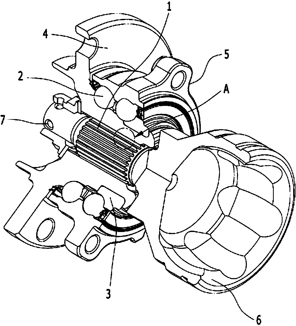
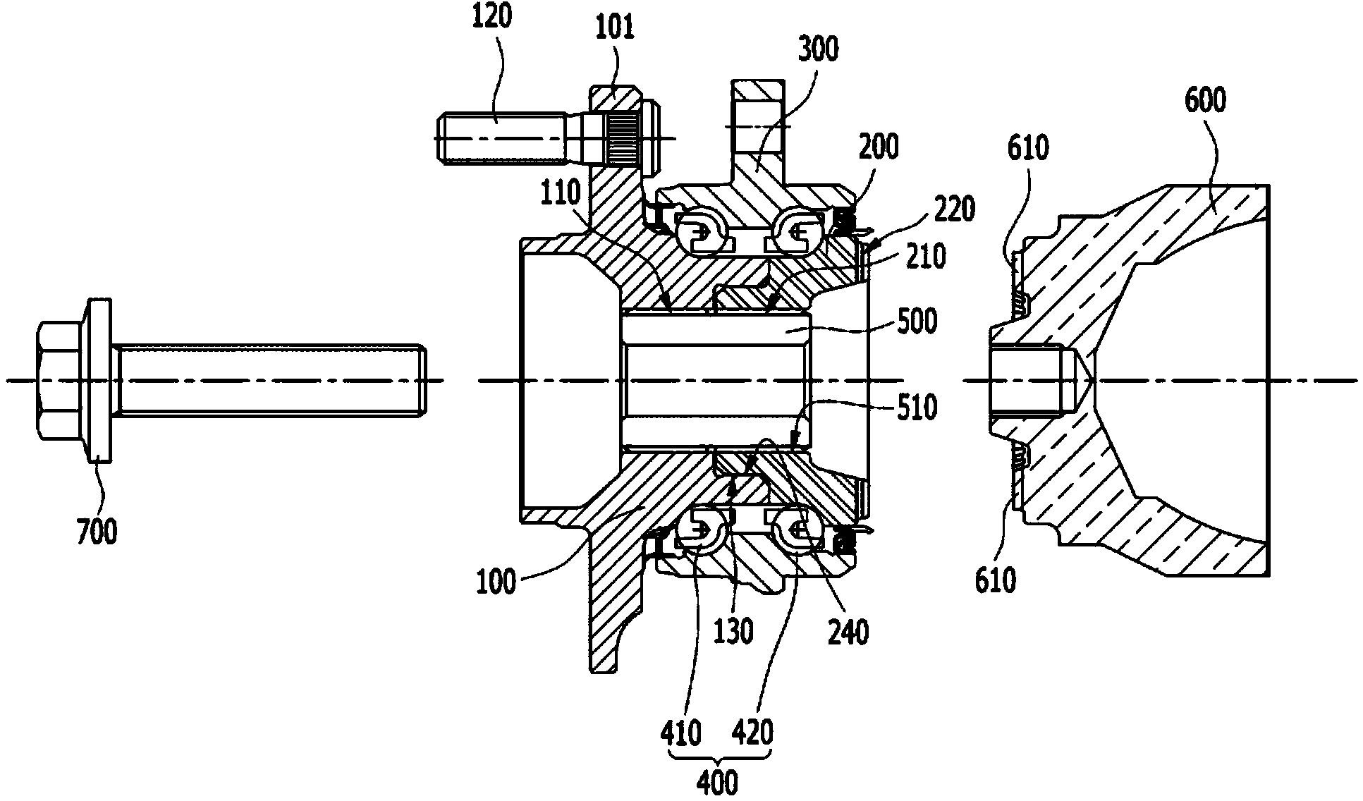
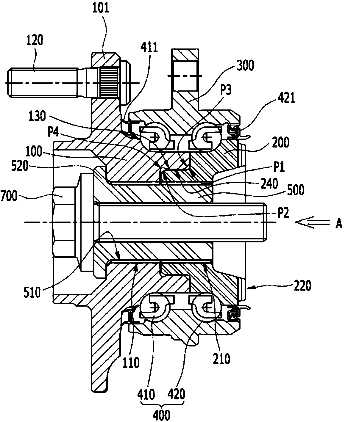
[0065] Figure 2 to Figure 6 A structure for coupling a wheel bearing according to a first exemplary embodiment of the present invention is shown.

[0066] Such as Figure 2 to Figure 6 As shown in , the structure for coupling wheel bearings according to the first exemplary embodiment of the present invention includes a hub 100 , an inner ring 200 , an outer ring 300 , rolling elements 400 , hollow pins 500 , joint members 600 and bolts 700 .

[0067] The hub 100 transmits driving torque of a joint member 600 such as a constant velocity joint (CVJ) to a vehicle wheel. The hub 100 is provided with a flange 101 and hub bolts 120 for mounting a vehicle wheel. Such as figure 2 As shown in , the flange 101 protrudes radially outward from the hub 100 and generally has a disc shape. A plurality of bolt holes are formed in the flange 101, ...


PUM


Abstract

The present invention relates to a structure and method for coupling a wheel bearing. The structure comprises: a wheel hub on which a vehicle wheel is mounted; a hollow inner wheel press-fitted into one side of the wheel hub; a ring-shaped outer wheel arranged outside the wheel hub and the inner wheel; and a rolling element interposed between the wheel hub or the inner wheel and the outer wheel. The wheel hub and the inner wheel are coupled together by a spline, and the inner wheel and a joint member are coupled together by a facial spline. According to the present invention, the driving force of a constant velocity joint can be stably transferred to the wheel hub, and noise can be reduced.

Description

technical field [0001] The present invention relates to a structure and method for coupling wheel bearings. More particularly, the present invention relates to a structure and method for coupling wheel bearings capable of improving the durability and quality of the wheel bearings. Background technique [0002] A wheel bearing used on an axle of a vehicle enables the vehicle wheel to rotate smoothly without friction loss and couples the vehicle wheel to the vehicle body. [0003] see figure 1 , figure 1 A cross-sectional view of a conventional vehicle bearing and a constant velocity joint assembled with each other is shown in . [0004] Such as figure 1 As shown in , a traditional wheel bearing includes a hub 4, an inner ring 3 press-fitted on the hub 4, an outer ring 5 arranged radially outside the inner ring 3, and a rolling mechanism provided between the inner ring 3 and the outer ring 5 element 2. In addition, a shaft of a constant velocity joint (CVJ) 6 is spline-c...

Claims


Application Information

Patent Timeline
Patent Type & Authority Applications(China)
IPC IPC(8): B60B35/18B60B35/00F16C43/04
CPCF16C43/04B60B27/0021B60B27/0036B60B27/0042F16C2226/52F16C2226/80F16C33/60F16C2326/02F16C2226/60F16C19/187F16C2226/12B60B2310/302B60B2310/311B60B2310/316B60B2900/321F16D1/076Y10T29/49689B60B27/0005B60B27/0078B60B2320/10B23P15/003B60B35/18
Inventor 宋在明尹希在房相知
Owner ILJIN GLOBAL
Why Eureka
Try Eureka