
Electric drive pump assembly

An electric drive and assembly technology, applied in engine components, pump/compressor arrangement, diaphragm valves, etc., can solve problems such as conflict of purpose and undesired cost, and achieve the effect of simplified structure and less pressure loss

Active Publication Date: 2017-03-08
CONTINENTAL AUTOMOTIVE TECH GMBH
View PDF3 Cites 0 Cited by
  • Summary
  • Abstract
  • Description
  • Claims
  • Application Information

AI Technical Summary

Problems solved by technology

The use of a separate pump assembly requires additional installation space and weight for itself as well as for the required electrical leads and low-pressure lines and connectors, the use of which leads to a conflict of objectives
Furthermore, the investment required in the manufacture and assembly of such an assembly leads to additional undesired costs

Method used


Image

  • Electric drive pump assembly
  • Electric drive pump assembly
  • Electric drive pump assembly

Examples


Embodiment Construction

[0042] figure 1

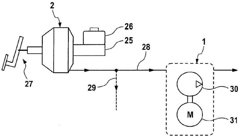
[0043] Pump unit 1 , which essentially includes pump 30 and electric pump drive unit 31 , is connected to pneumatic brake booster 2 via a low-pressure line 28 . In this case, a low-pressure line 28 pneumatically connects a not-shown low-pressure chamber of the brake booster 2 and a not-shown inlet channel 8 of the pump unit 1 to one another, whereby air can be drawn from the low-pressure chamber. Exhaust through pump assembly 1. In addition, the brake booster 2 can be connected to a further low-pressure line 29 which is connected, for example pneumatically, to the suction line of the internal combustion engine and which also serves to remove air from the brake booster 2 . . In the sketch shown, the main brake cylinder 25 is arranged on the brake booster 2, the pressure medium container 26 is hydraulically connected to the main brake cylinder 25, it is not important here that the pressure medium container 26 is as shown directly or via a remote line to the...


PUM


Abstract

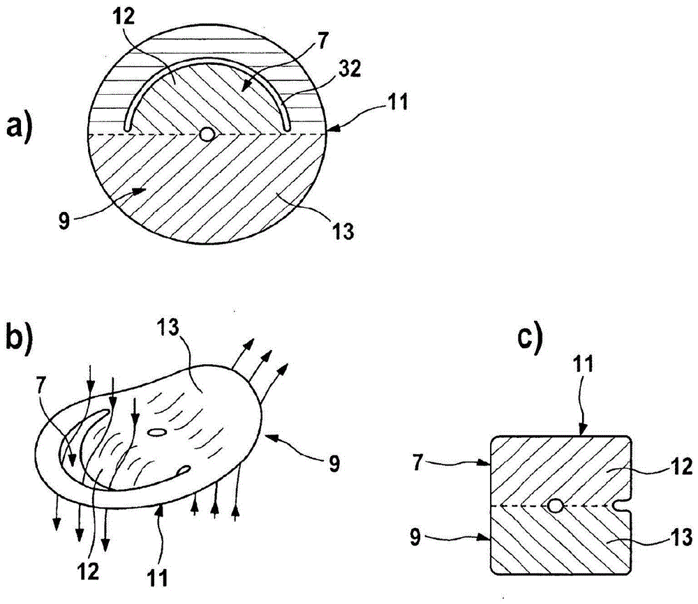
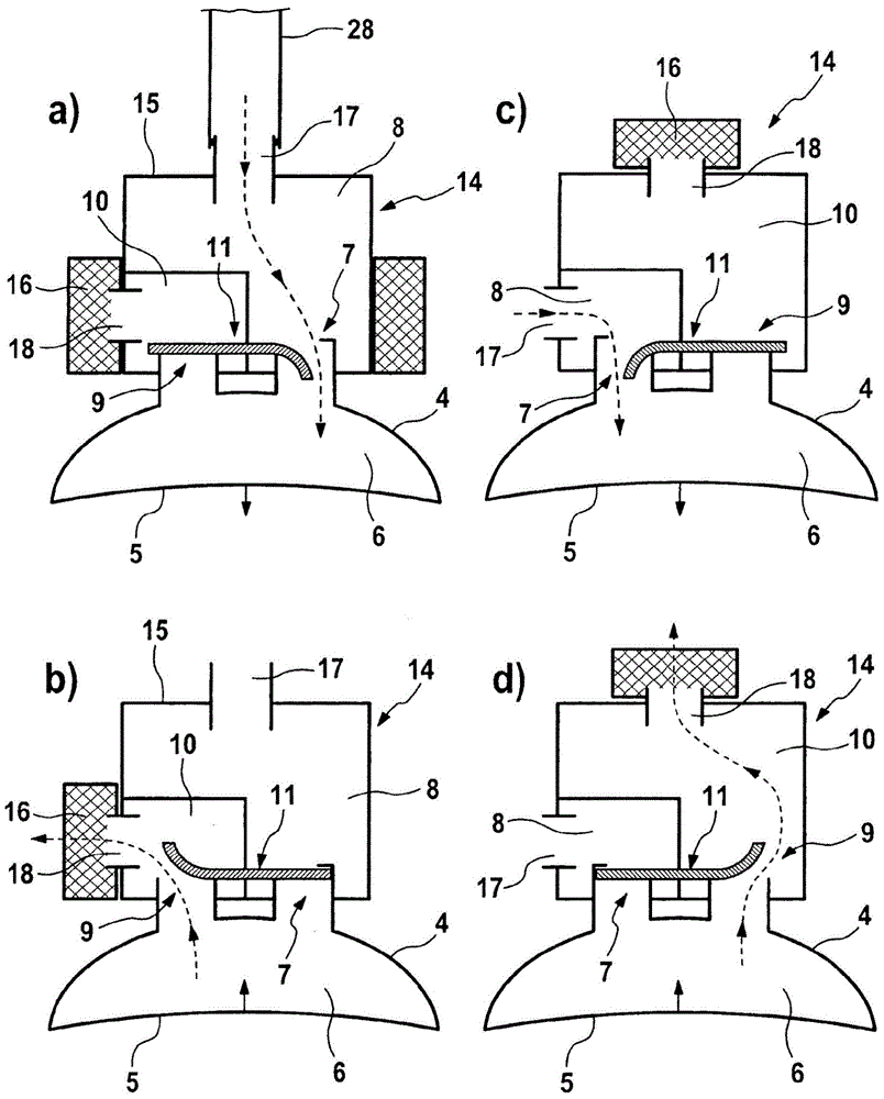
The invention relates to a pump unit (1) driven by an electric motor for providing vacuum for a pneumatic brake booster (2) of a motor vehicle brake system, wherein the pump unit (1) has a pump housing (3) and at least one elastic displacement element (5) for displacing a working medium, wherein the pump housing (3) is closed off by at least one working chamber cover (4) such that a working chamber (6) is delimited between the displacement element (5) and the working chamber cover (4), wherein at least one inlet valve (7) with an inlet channel (8) and at least one outlet valve (9) with an outlet channel (10) are associated with the working chamber (6), and wherein the valves (7, 9) can each be shifted automatically by means of pressure difference from a closed non-actuated starting position into an open actuating position. In order to offer a cost-effective and particularly compact pump unit, which has a reduced weight and is improved in terms of ease of production and assembly, according to the invention the inlet valve (7) and the outlet valve (9) are formed by a one-piece elastic element (11).

Description

technical field [0001] The invention relates to an electrically driven pump assembly for supplying a low pressure for a pneumatic brake booster of a motor vehicle braking system, wherein the pump assembly has a pump housing and at least one pump for displacement work An elastic displacement element of the medium, wherein the pump housing is closed by at least one working chamber cover, whereby a working chamber is defined between the displacement element and the working chamber cover, wherein the working chambers are respectively At least one inlet valve with an inlet channel and at least one outlet valve with an outlet channel are provided, wherein the inlet valve and the outlet valve each move automatically from a closed, unactuated initial position to an open position controlled by a pressure difference. in the operating position. Background technique [0002] In motor vehicles with pneumatically amplified hydraulic braking systems, especially when using diesel, turbocha...

Claims


Application Information

Patent Timeline
Patent Type & Authority Patents(China)
IPC IPC(8): B60T17/02F16K7/12F16K7/17
CPCF16K15/144B60T17/02
Inventor F·佩佐尔德
Owner CONTINENTAL AUTOMOTIVE TECH GMBH
Learn More