
Hydraulic drive device of construction machine

A technology for driving devices and construction machinery, applied in fluid pressure actuating devices, mechanical equipment, earth movers/shovels, etc., can solve problems such as high load pressure, damage to operation feeling, and discharge flow capture, etc., and achieve good results. The effect of compound operability

Active Publication Date: 2014-12-24
NIHON KENKI CO LTD
View PDF7 Cites 6 Cited by
  • Summary
  • Abstract
  • Description
  • Claims
  • Application Information

AI Technical Summary

Problems solved by technology

[0014] However, in the hydraulic drive device described in Patent Document 2, there is a problem that in the case of saturation due to combined operation in which the difference in load pressure of the two actuators is further increased, the discharge flow rate of the main pump will be reduced. Mostly captured by the actuator on the low load pressure side, the actuator on the high load pressure side will stall
[0016] Furthermore, if the blade is suddenly operated during driving and the blade is operated in combination, the hydraulic oil will instantly flow to the blade hydraulic cylinder, thereby decelerating and stopping the driving, which will impair the operating feeling.
[0017] Even in addition to the travel motor, for example, a spare actuator included in an additional device such as a pulverizer that is used in place of a bucket, the load pressure becomes higher in many cases, and the difference in load pressure will be caused by other actuators (such as Boom, arm, and bucket hydraulic cylinders) are enlarged by combined operations, and the same problem occurs

Method used


Image

  • Hydraulic drive device of construction machine
  • Hydraulic drive device of construction machine
  • Hydraulic drive device of construction machine

Examples


no. 1 approach

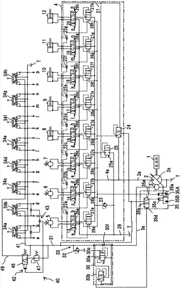
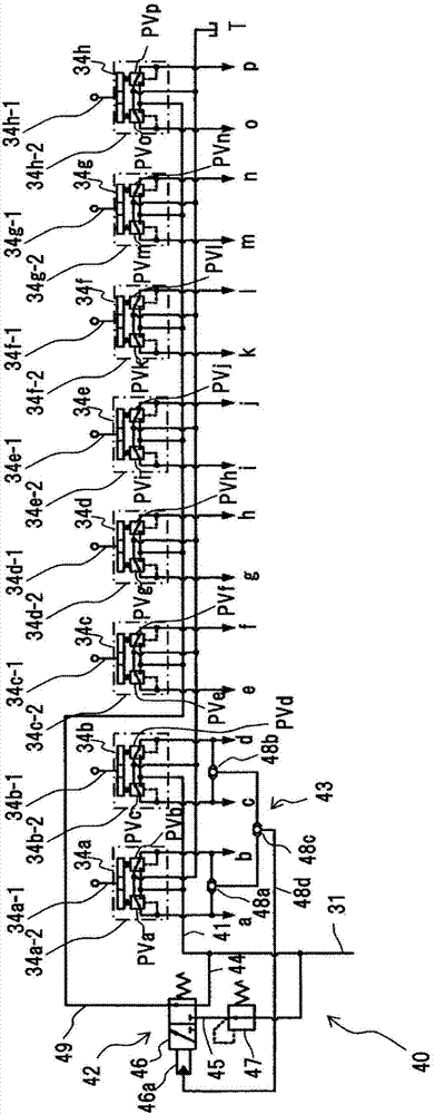
[0048] exist Figure 1A A hydraulic drive device for a hydraulic excavator according to a first embodiment of the present invention is shown in the figure.

[0049] ~Basic composition~

[0050] First, the basic configuration of the hydraulic drive device of the present embodiment will be described.

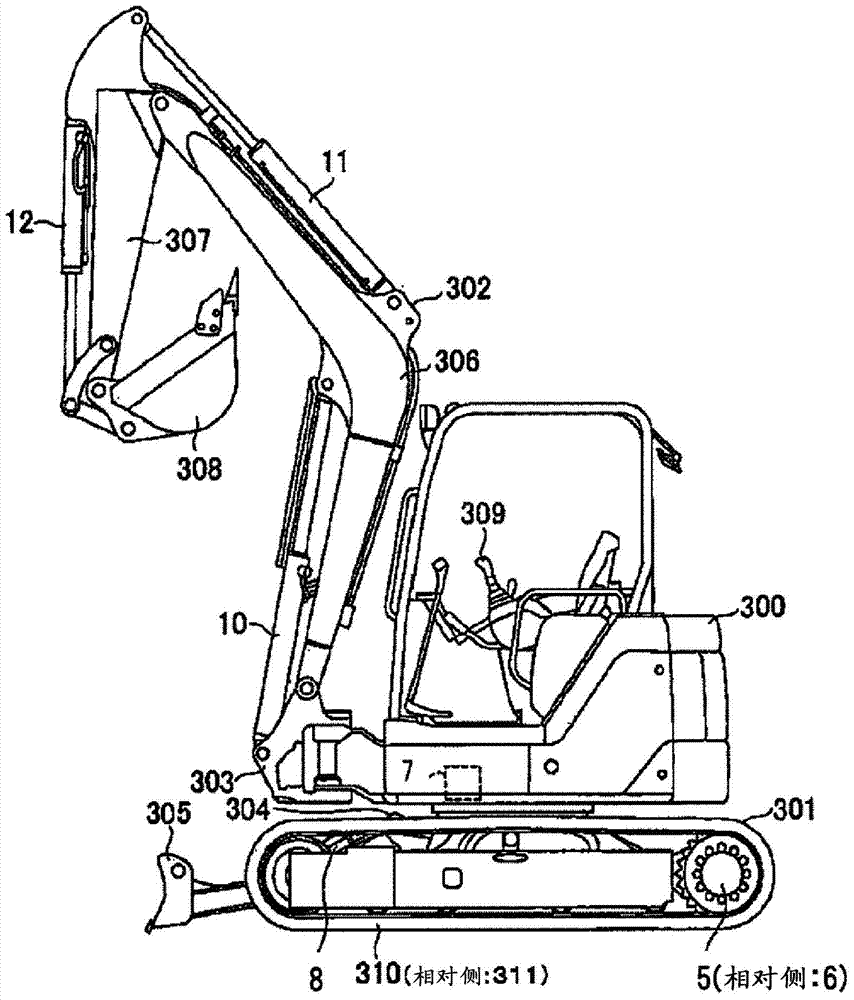
[0051] The hydraulic drive device of this embodiment has: an engine 1; a main hydraulic pump (hereinafter referred to as the main pump) 2 driven by the engine 1; a pilot pump 3 driven by the engine 1 in conjunction with the main pump 2; Left and right travel motors 5, 6, swing motors 7, blade hydraulic cylinders 8, swing hydraulic cylinders 9, boom hydraulic cylinder 10 , arm hydraulic cylinder 11 , bucket hydraulic cylinder 12 ; and control valve 4 . The hydraulic excavator of this embodiment is, for example, a mini hydraulic excavator.

[0052] The control valve 4 has: a plurality of valve sections (valve sections) 13, 14, 15, 16, 17, 18, 19, 20, which are connected to the su...

no. 2 approach

[0112] exist Figure 4 The figure shows the operating device and its pilot circuit part in the hydraulic drive system of the hydraulic excavator according to the second embodiment of the present invention. In the figure, for and in Figure 1B Components that are the same as those shown in , are assigned the same reference numerals, and description thereof will be omitted. The present embodiment differs from the first embodiment in the configuration for reducing the pilot primary pressure and the configuration for switching the pilot primary pressure.

[0113] That is, the hydraulic drive device of this embodiment has a pilot primary pressure circuit 40A, and the second circuit 42A of the pilot primary pressure circuit 40A has: a fifth circuit 52 having a pilot-operated pressure reducing valve 51; and a sixth circuit 54, It has a switching valve 53 that switches the pilot pressure guided to the pilot pressure receiving portion 51a of the pilot-operated pressure reducing valve...

no. 3 approach

[0118] exist Figure 5 The figure shows the operating device and its pilot circuit part in the hydraulic drive system of the hydraulic excavator according to the third embodiment of the present invention. In the figure, for and in Figure 1B Components that are the same as those shown in , are assigned the same reference numerals, and description thereof will be omitted. In this embodiment, the configuration (fourth circuit) for depressurizing the pilot primary pressure is different from that of the first embodiment.

[0119] That is, the hydraulic drive device of this embodiment has a pilot primary pressure circuit 40B, and the second circuit 42B of the pilot primary pressure circuit 40B has: a third circuit 61 that guides the pilot primary pressure without change; a fourth circuit 62 that guides the pilot primary pressure and the switching valve 63 switches the pressure of the third circuit 61 and the pressure of the fourth circuit 62 to guide the remote control valve of t...


PUM


Abstract

A pressure compensation valve that does not fully close at stroke end is used and a travel operation is performed, whereupon pilot primary pressure is reduced and supplied to the remote control valves (34c-34h) of a non-travel operation device. The inflow of pressure oil to a non-travel actuator in a travel composite operation is thereby suppressed, and a travel motor is ensured the necessary amount of pressure oil. When there is saturation in a composite operation such that there is a large difference between the load pressure of two actuators in the hydraulic drive device of a construction machine in which load sensing control is performed, the pressure compensation valve having the lower load pressure is thereby prevented from closing to prevent deceleration or stopping of the actuator having the lower load pressure, the actuator having the higher load pressure is ensured to have the necessary amount of pressure oil to prevent deceleration or stopping of the higher-load-pressure actuator, and satisfactory composite operability is achieved.

Description

technical field [0001] The present invention relates to a hydraulic driving device for construction machinery such as a hydraulic excavator, and more particularly to a hydraulic driving device for a construction machine whose load sensing controls the discharge flow rate of a hydraulic pump so that the discharge pressure of the hydraulic pump is higher than that of a plurality of actuators. The peak load pressure is only above the target differential pressure. Background technique [0002] In the hydraulic drive unit of construction machinery such as hydraulic excavators, there is a device that controls the discharge flow rate of the hydraulic pump so that the discharge pressure of the hydraulic pump (main pump) is higher than the maximum load pressure of multiple actuators by a target differential pressure, and this control is called load sensing control. In the hydraulic drive device that performs this load sensing control, the pressure difference between the front and re...

Claims


Application Information

Patent Timeline
Patent Type & Authority Applications(China)
IPC IPC(8): F15B11/08E02F9/22F15B11/02F15B11/05
CPCE02F9/2285E02F9/2296F15B11/166E02F3/325F15B2211/20553F15B2211/30535F15B2211/329F15B2211/355F15B2211/6055F15B2211/6058F15B2211/6355F15B2211/7058F15B2211/7135F15B2211/781E02F9/2203E02F9/2225F15B9/03F15B9/08F15B13/06F15B2211/6051
Inventor 竹林圭文高桥究森和繁中村夏树
Owner NIHON KENKI CO LTD
Learn More