
Tool group of tillage machine

A technology of cultivating machines and knives, which is applied in the fields of tillage machines, agricultural machinery and tools, etc. It can solve the problems of intermittent large impact force, increased unit vibration, incomplete stubble removal, etc., and achieve the goal of overcoming severe impact and beating Effect

Inactive Publication Date: 2014-12-31
泰州樱田农机制造有限公司
View PDF0 Cites 2 Cited by
  • Summary
  • Abstract
  • Description
  • Claims
  • Application Information

AI Technical Summary

Problems solved by technology

The knife holders of the existing cultivator cutter sets are distributed and welded on the cutter shaft in a straight line. The intermittent impact force of this kind of tiller cutter set is very large during operation, resulting in increased vibration of the unit and incomplete stubble removal.

Method used


Image

  • Tool group of tillage machine

Examples


Embodiment Construction

[0014] The present invention will be further described below according to the accompanying drawings and in conjunction with the embodiments.

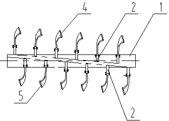
[0015] The cultivator knife set shown in the accompanying drawings includes a frame cutter shaft 1, a knife seat 2, a left curved blade 5, and a right curved blade 4; the knife seat 2 is fixedly connected to the knife shaft 1, and the left curved blade 5 and the right curved blade 4 is fixedly connected in the knife seat 2; the knife seat 2 for fixing the left curved blade 5 and the knife seat 2 for fixing the right curved blade 4 are respectively arranged along the helical line of the outer wall of the knife shaft 1 in the same direction of rotation.

[0016] In this embodiment, the pitch of the two helical lines is the same, and the helix angle of the two helical lines is 5°. The knife seat 2 for fixing the left curved blade 5 and the knife seat 2 for fixing the right curved blade 4 are respectively along the spiral Arranged at eq...


PUM


Abstract

The invention discloses a tool group of a tillage machine. The tool group comprises a rack tool shaft, tool bases, left curved blades and right curved blades, wherein the tool bases are fixedly connected with the tool shaft; the left curved blades and the right curved blades are fixedly connected in the tool bases; the tool bases for fixing the left curved blades and the tool bases for fixing the right curved blades are respectively distributed along spiral lines with the same spiral direction of outer walls of the tool shaft; the improvements are as follows: the two spiral lines for distributing the tool bases for fixing the left curved blades and the tool bases for fixing the right curved blades are the same in helical pitch, and the helix angles are 5-15 degrees; the tool bases for fixing the left curved blades and the tool bases for fixing the right curved blades are respectively arranged at equal intervals along the spiral lines; the left curved blades and the right curved blades are sequentially arranged in a staggered manner. The tool group has the advantages that the use effect of the tool group of the tillage machine is greatly improved, the tillage flatness degree is good, the working stability is enhanced, and loads of the tool shaft are uniform.

Description

technical field [0001] The invention relates to a tiller cutter set. Background technique [0002] With the development of agriculture, cultivators are widely used in agricultural production. The knife seats of the existing cultivator cutter sets are all welded on the cutter shaft in a linear manner. The intermittent impact force of this tiller cutter set is very large during operation, resulting in increased vibration of the unit and incomplete stubble removal. Contents of the invention [0003] Aiming at the deficiencies of the prior art, the invention proposes a cultivator cutter set capable of improving working stability and ensuring uniform load on the cutter shaft. [0004] The present invention achieves technical goals through the following technical solutions. [0005] Tillage machine tool set, including frame cutter shaft, knife seat, left curved blade, right curved blade; the knife seat is fixedly connected to the knife shaft, and the left curved blade and righ...

Claims


Application Information

Patent Timeline
Patent Type & Authority Applications(China)
IPC IPC(8): A01B33/10
Inventor 曹冬林
Owner 泰州樱田农机制造有限公司
Learn More