Diffusion rectification flow equalizing structure

A technology of diffuser tube and rectifier plate, applied in the direction of fluid flow, pipe/pipe joint/pipe fitting, mechanical equipment, etc., can solve the problems of high flow velocity in the center of the heating cavity, large impact load of equipment, and reduced heat exchange efficiency, and achieve heat exchange. Efficiency improvement, overcoming large shock loads, and consistent flow rate

Active Publication Date: 2021-04-23
AVIC SHENYANG AERODYNAMICS RES INST +1
View PDF19 Cites 0 Cited by
  • Summary
  • Abstract
  • Description
  • Claims
  • Application Information

AI Technical Summary

Problems solved by technology

[0002] The electric heater is one of the important devices in the test of aero-engine and components, and it has extremely high requirements on the uniformity of the medium flow during the heating process; but usually, the cross-sectional area of ​​the inlet pipe of the electric heater The cross-sectional area of ​​the cylinder body is much smaller. In this case, the flow channel is embodied as a sudden expansion structure, so that the central flow velocity in the heating chamber is extremely high, while the surrounding flow velocity is extremely low, resulting in excessive impact load of the medium on the equipment. Disadvantages such as decreased heat transfer efficiency

Method used


Image

  • Diffusion rectification flow equalizing structure
  • Diffusion rectification flow equalizing structure
  • Diffusion rectification flow equalizing structure

Examples


Embodiment Construction

[0027] The specific implementation manner of the present invention will be described below in conjunction with the accompanying drawings.

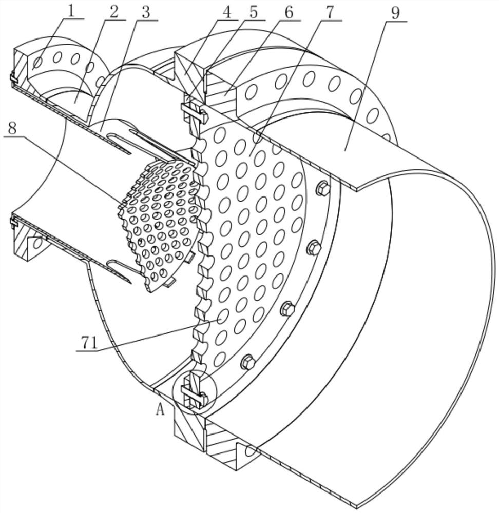
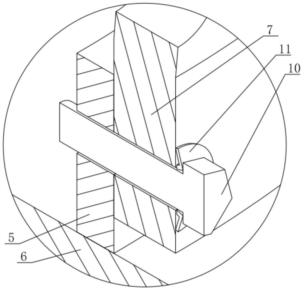
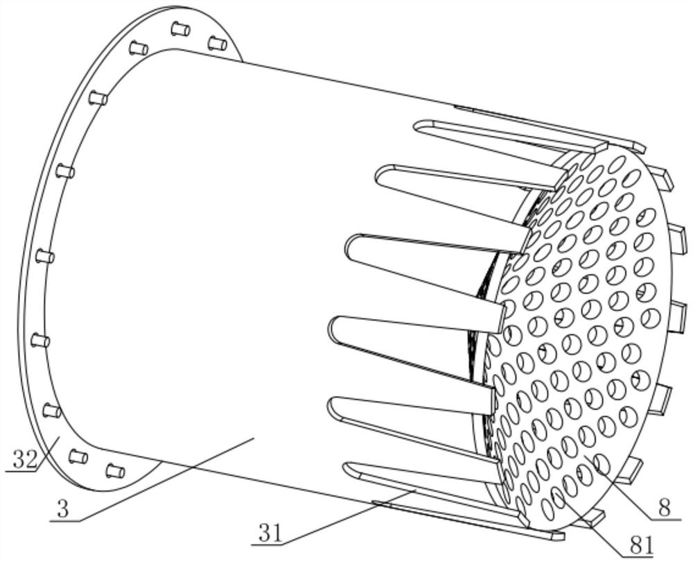
[0028] Such as figure 1 As shown, a diffusion and rectification flow equalization structure of the present embodiment includes a front-to-back through shell, a diffuser tube 3 is installed in the front opening of the shell, and a concave diffuser cone 8 is installed at the rear end of the diffuser tube 3 A rectifying plate 7 is installed on the inner wall of the housing behind the diffuser 3, and the housing behind the rectifying plate 7 is connected with a heating chamber; the edge of the diffuser 3 and the diffuser cone 8, the diffuser 8 and the rectifier 7 are provided with through holes for medium circulation; the middle part of the rectifying plate 7 protrudes into a tapered structure, and the surrounding edges of the rectifying plate 7 are connected to the inner wall of the housing through fasteners arranged at intervals. Disc sprin...


PUM


Abstract

The invention relates to a diffusion rectification flow equalizing structure. The diffusion rectification flow equalizing structure structure comprises a shell which is through in the front-back direction, a diffusion pipe is installed at an opening in the front end of the shell in a lining mode, a concave diffusion cone is installed at the rear end of the diffusion pipe, a rectifying plate is installed on the inner wall, located behind the diffusion pipe, of the shell, and the shell located behind the rectifying plate communicates with a heating cavity. Through holes for medium circulation are formed in the edge, connected with the diffusion cone, of the diffusion pipe, the diffusion cone and the rectifying plate. The middle of the rectifying plate protrudes backwards to form a conical structure, and the peripheral edge of the rectifying plate is connected with the inner wall face of the shell through fasteners arranged at intervals. A medium enters from the front end of the diffusion pipe, one part of the medium horizontally enters the shell through the through holes in the diffusion cone, the other part of the medium diffuses under the conical surface flow guide effect of the diffusion cone and enters the shell through the through holes in the diffusion pipe, the medium entering the shell flows to the rear heating cavity through the through holes in the rectifying plate, diffusion and rectification of the medium are completed, so that the flow equalization and stabilization of the medium are realized in a short distance, and the practicability is good.

Description

technical field [0001] The invention relates to the technical field of electric heaters, in particular to a diffusion and rectification current equalization structure. Background technique [0002] The electric heater is one of the important devices in the test of aero-engine and components, and it has extremely high requirements on the uniformity of the medium flow during the heating process; but usually, the cross-sectional area of ​​the inlet pipe of the electric heater The cross-sectional area of ​​the cylinder body is much smaller. In this case, the flow channel is embodied as a sudden expansion structure, so that the central flow velocity in the heating chamber is extremely high, while the surrounding flow velocity is extremely low, resulting in excessive impact load of the medium on the equipment. Disadvantages such as reduced heat transfer efficiency. Contents of the invention [0003] In view of the shortcomings in the above-mentioned existing production technolo...

Claims


Application Information

Patent Timeline
Patent Type & Authority Applications(China)
IPC IPC(8): F16L55/027F15D1/02
Inventor 辛亚楠高亮杰袁野刘帅白旭赵钧王春花赵成旺
Owner AVIC SHENYANG AERODYNAMICS RES INST
Why Eureka
Try Eureka