a polishing machine

A polishing machine and polishing roller technology, which is applied in the field of polishing machines, can solve the problems of high energy consumption, unsatisfactory, and small polishing machine output, and achieve the effect of reducing energy consumption and increasing output

Active Publication Date: 2016-08-17
湖北天明粮油设备有限公司
View PDF3 Cites 0 Cited by
  • Summary
  • Abstract
  • Description
  • Claims
  • Application Information

AI Technical Summary

Problems solved by technology

Therefore, it cannot meet the requirements of processing different materials with the same polishing machine
Moreover, the output of the existing polishing machine is small and the energy consumption is high

Method used


Image

  • a polishing machine
  • a polishing machine
  • a polishing machine

Examples


Embodiment Construction

[0028] The present invention will be further described below in conjunction with the accompanying drawings and specific embodiments.

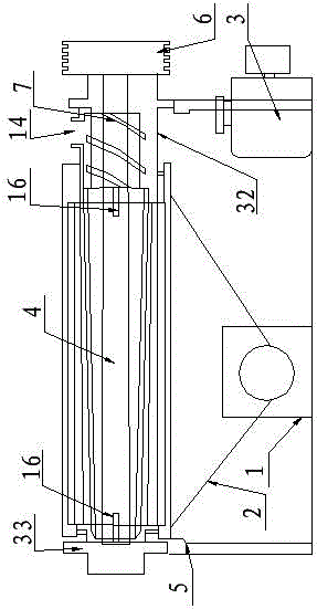
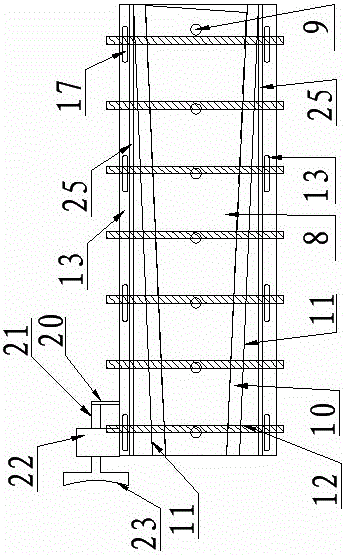
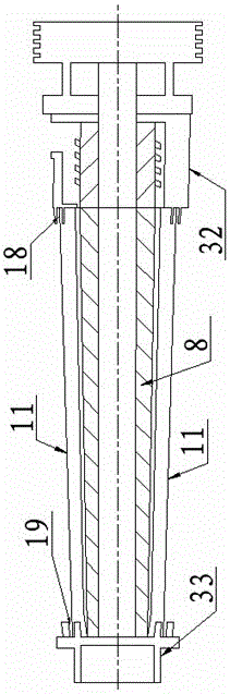
[0029] Such as figure 1 , 2 , a kind of polishing machine shown in 3,4,5, comprises frame 5, blower fan 1, chaff collecting bucket 2, motor 3, main shaft 4 is horizontally arranged along frame 5, motor 3 is connected with main shaft 4 by belt pulley 6, main shaft 4 is a hollow tube structure, the main shaft 4 is connected with a propeller 7 and a polishing roller 8, and the two ends of the polishing roller 8 are provided with inlet and outlet bearing seats 18, 19, and the polishing roller 8 is provided with a ventilation groove 9. Between the polishing roller 8 and the sieve plate 11 is a polishing chamber 10, the sieve plate 11 is fixed on the inner side of the sieve bracket 12, the two ends of the sieve bracket 12 are fixed on the beam 13 by bolts, the feed port 14 is located above the propeller 7, and the outlet The feed port 15 is located...


PUM


Abstract

The invention relates to the field of rice processing machinery, and provides a polishing machine, which includes a frame, the main shaft is arranged horizontally along the frame, a polishing roller is connected outside the main shaft, and both ends of the polishing roller are provided with inlet and outlet bearing seats, and the polishing roller is in the shape of Conical shape, the sieve plate is adapted to the side of the polishing roller, the beam of the frame is provided with waist-shaped holes for the fixing bolts of the sieve bracket, and the two ends of the sieve plate are embedded in the concave holes of the inlet and outlet bearing seats. In the groove, the groove of the inlet and outlet bearing seats is the same as the slope of the side of the polishing roller. The device of the invention can adjust the distance between the polishing roller and the sieve plate, so that the same polishing machine can meet the polishing requirements of various granular crops, and has large output and low energy consumption.

Description

technical field [0001] The invention relates to the field of rice processing machinery, in particular to a polishing machine. Background technique [0002] Polishing machines are widely used in rice and various grain processing fields, and the market demand is large. It is supported by a frame, a main shaft crosses the frame, a propeller and a polishing roller are installed on the main shaft, which constitutes the rotating part of the machine, and a sieve plate and a sieve bracket are installed outside the polishing roller, and the sieve bracket The center and the center of the main shaft are concentric, and the space between the polishing roller and the sieve plate forms a polishing room, and the grain is polished in the polishing room to improve the smoothness and brightness of the grain surface. [0003] The size of the polishing chamber of the existing polishing machine is fixed, that is, the distance between the polishing roller and the sieve plate is fixed, but there ...

Claims


Application Information

Patent Timeline
Patent Type & Authority Patents(China)
IPC IPC(8): B02B3/04B02B7/00B02B7/02
Inventor 郑仁明吴湘萍
Owner 湖北天明粮油设备有限公司
Why Eureka
Try Eureka