
Track shoe pin hole machining equipment

A technology for processing equipment and track shoes, which is applied to metal processing equipment, metal processing machinery parts, manufacturing tools, etc., and can solve problems such as abnormal noise, cracking, and low precision of pin holes on track pins

Active Publication Date: 2014-12-31
ZOOMLION HEAVY IND CO LTD
View PDF13 Cites 16 Cited by
  • Summary
  • Abstract
  • Description
  • Claims
  • Application Information

AI Technical Summary

Problems solved by technology

[0002] At present, the tracks in the heavy-duty crawler chassis of construction machinery are generally connected by casting track shoes. The accuracy of the pin holes of the track shoes is completely controlled by casting, so the accuracy of the pin holes is usually low, resulting in uneven meshing when the track is walking. , abnormal noise, and cracking of track pins due to uneven force
Therefore, in order to improve the linking accuracy of the track shoe, it is necessary to finish the track shoe pin hole, for example, to optimize the parallelism, coaxiality and cylindricity of the track shoe pin hole. The pin holes on the track shoe are intermittent elongated holes. The existing machining methods are, for example, using lathe transformation or floor boring machine for processing. The processing efficiency is low, and the parallelism, coaxiality and cylindricity of the track shoe pin holes are not easy to obtain. Guaranteed, and the inner surface of the pin hole is rough, in other words, the existing form of using the general machine tool to process the pin hole of the track shoe is difficult to meet the requirements of convenience, high efficiency and economy for the finishing of the track shoe pin hole, the purpose of the present invention is to solve above question

Method used


Image

  • Track shoe pin hole machining equipment
  • Track shoe pin hole machining equipment
  • Track shoe pin hole machining equipment

Examples


Embodiment Construction

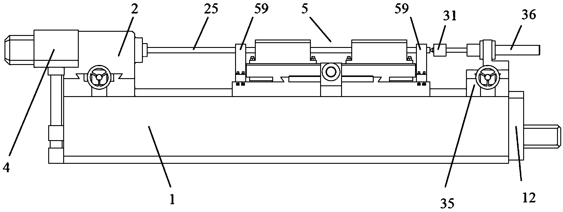
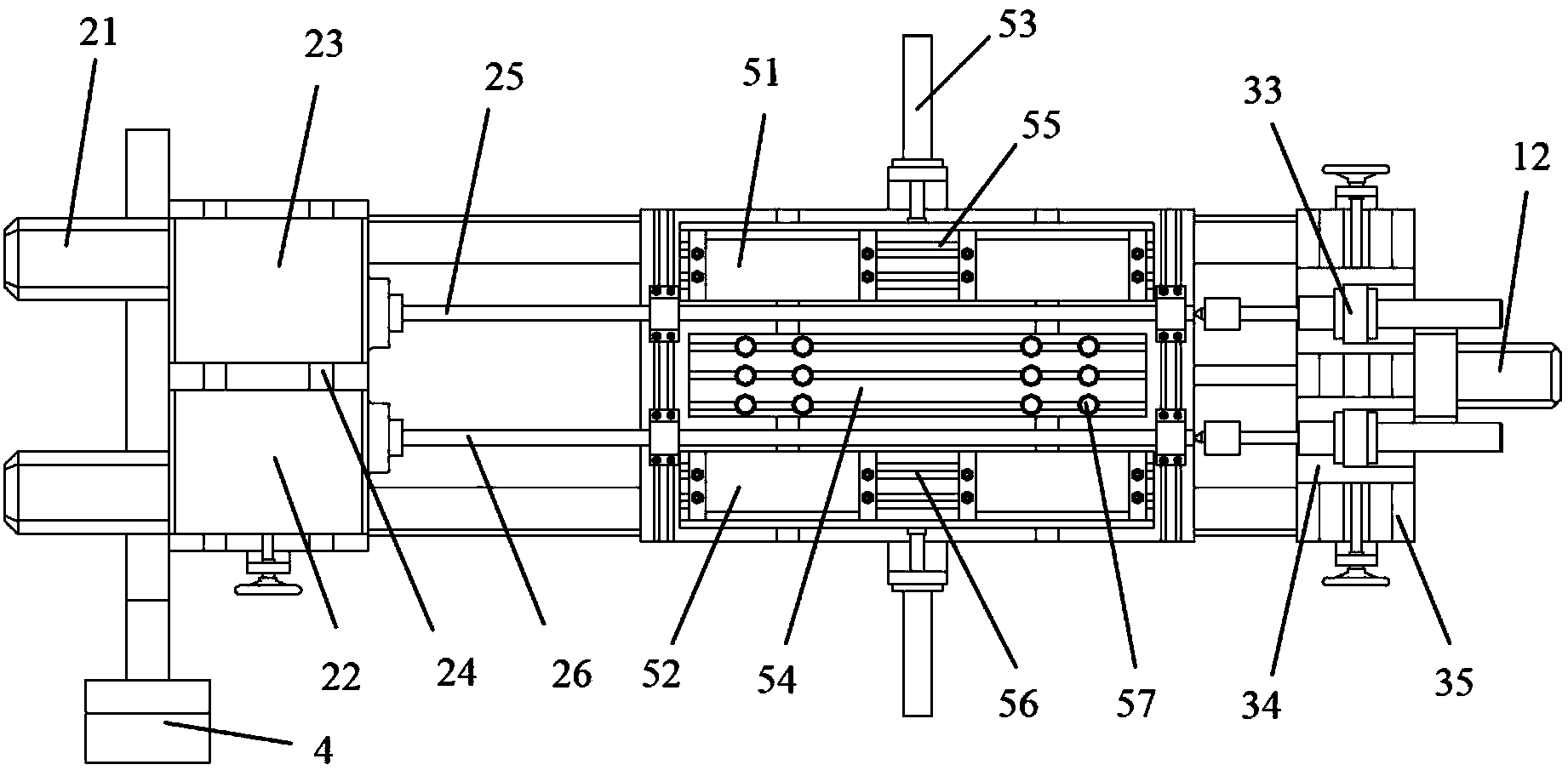
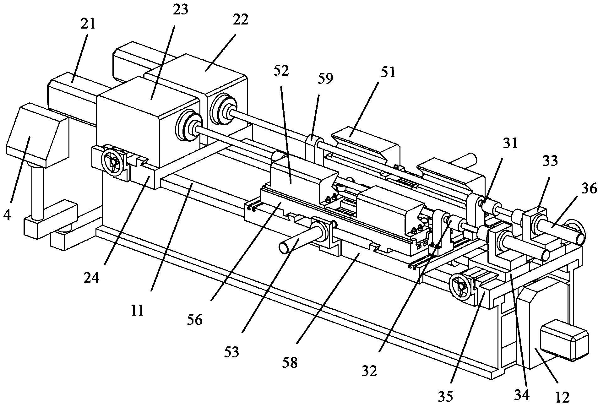
[0047] Specific embodiments of the present invention will be described in detail below in conjunction with the accompanying drawings. It should be understood that the specific embodiments described here are only used to illustrate and explain the present invention, and are not intended to limit the present invention.

[0048] In the present invention, unless stated otherwise, the used orientation words such as "upper and lower" are generally defined in the normal use of the track shoe pin hole processing equipment provided by the present invention, and are also used with reference to The directions shown in the figure are consistent; "inside and outside" refer to the inside and outside relative to the contour of each part itself; and wherein, "the longitudinal direction of the processing equipment" refers to the length direction of the track shoe pin hole processing equipment of the present invention ( figure 1 with figure 2 The left and right direction of the processing equ...


PUM


Abstract

The invention discloses track shoe pin hole machining equipment. The track shoe pin hole machining equipment comprises a base, and a clamping mechanism, a machining mechanism and a feeding mechanism mounted on the base. The clamping mechanism is used for clamping track shoes and keeping the track shoes in the machining direction, the machining mechanism is used for machining pin holes, the feeding mechanism is used for enabling the clamping mechanism and the machining mechanism to move relatively after the track shoes are kept in the machining direction, and the machining mechanism machines the pin holes in the track shoes kept in the machining direction in the process of relative movement of the clamping mechanism and the machining mechanism. The track shoe pin hole machining equipment is specially used for machining the pin holes of the track shoes, the track shoes are kept in the machining direction through the clamping mechanism according to the unique structural design of the track shoes, then the pin holes of the track shoes kept in the machining direction are subjected to finish machining through the machining mechanism, and machining efficiency and effect can be improved effectively.

Description

technical field [0001] The invention relates to the field of mechanical processing, in particular to a track shoe pin hole processing equipment. Background technique [0002] At present, the tracks in the heavy-duty crawler chassis of construction machinery are generally connected by casting track shoes. The accuracy of the pin holes of the track shoes is completely controlled by casting, so the accuracy of the pin holes is usually low, resulting in uneven meshing when the track is walking. , Abnormal noise, and cracking of track pins due to uneven force. Therefore, in order to improve the linking accuracy of the track shoe, it is necessary to finish the track shoe pin hole, for example, to optimize the parallelism, coaxiality and cylindricity of the track shoe pin hole. The pin holes on the track shoe are intermittent elongated holes. The existing machining methods are, for example, using lathe transformation or floor boring machine for processing. The processing efficienc...

Claims


Application Information

Patent Timeline
IPC IPC(8): B23D79/00B23Q3/06B23Q5/40
Inventor 罗凯高一平何光辉席传让田湘龙
Owner ZOOMLION HEAVY IND CO LTD
Learn More