Method and device for separating gases

A gas and inlet gas technology, applied in separation methods, semi-permeable membrane separation, nitrogen purification/separation, etc., can solve problems such as inability to build, ineffective solutions, and inability to prevent gas purity problems, so as to save energy and avoid leakage losses Effect

Inactive Publication Date: 2014-12-31
ATLAS COPCO AIRPOWER NV
View PDF10 Cites 1 Cited by
  • Summary
  • Abstract
  • Description
  • Claims
  • Application Information

AI Technical Summary

Problems solved by technology

[0011] This method has the disadvantage that it only works with speed-controlled compressors, not with compressor types that are otherwise controlled
[0016] This solution also has the disadvantage that it is not effective if the compressor plant supplies other equipment (which has its own requirements, such as the compressed air network) in addition to the diaphragm unit
[0019] This device has the disadvantage that it is not possible to control the product gas flow as a result
[0022] Conventional installations including said improvements all have the disadvantage that if the discharge of product gas is greater than the design capacity of the plant, the purity becomes lower than the design value
[0023] Furthermore, the improvement does not prevent excessive product gas purity problems when product gas emissions are low
[0024] When a specific type of compressor other than the controllable compressor is used, the control of the compressor is also complicated or cannot be constructed, and when different types of compressors are used in one compressor device , it must not be possible to construct such a control
[0025] Also, known solutions to control purity do not take into account important aspects of compressor operation, such as minimum energy consumption, maximum service life, and optimum maintenance intervals, all of which are strongly influenced by compressor operating conditions

Method used


Image

  • Method and device for separating gases
  • Method and device for separating gases
  • Method and device for separating gases

Examples


Embodiment Construction

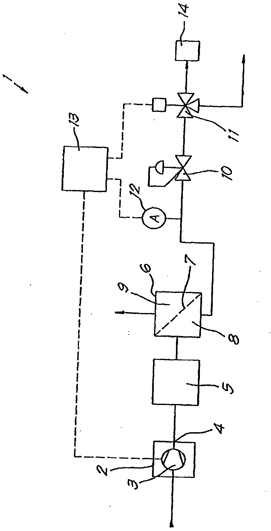
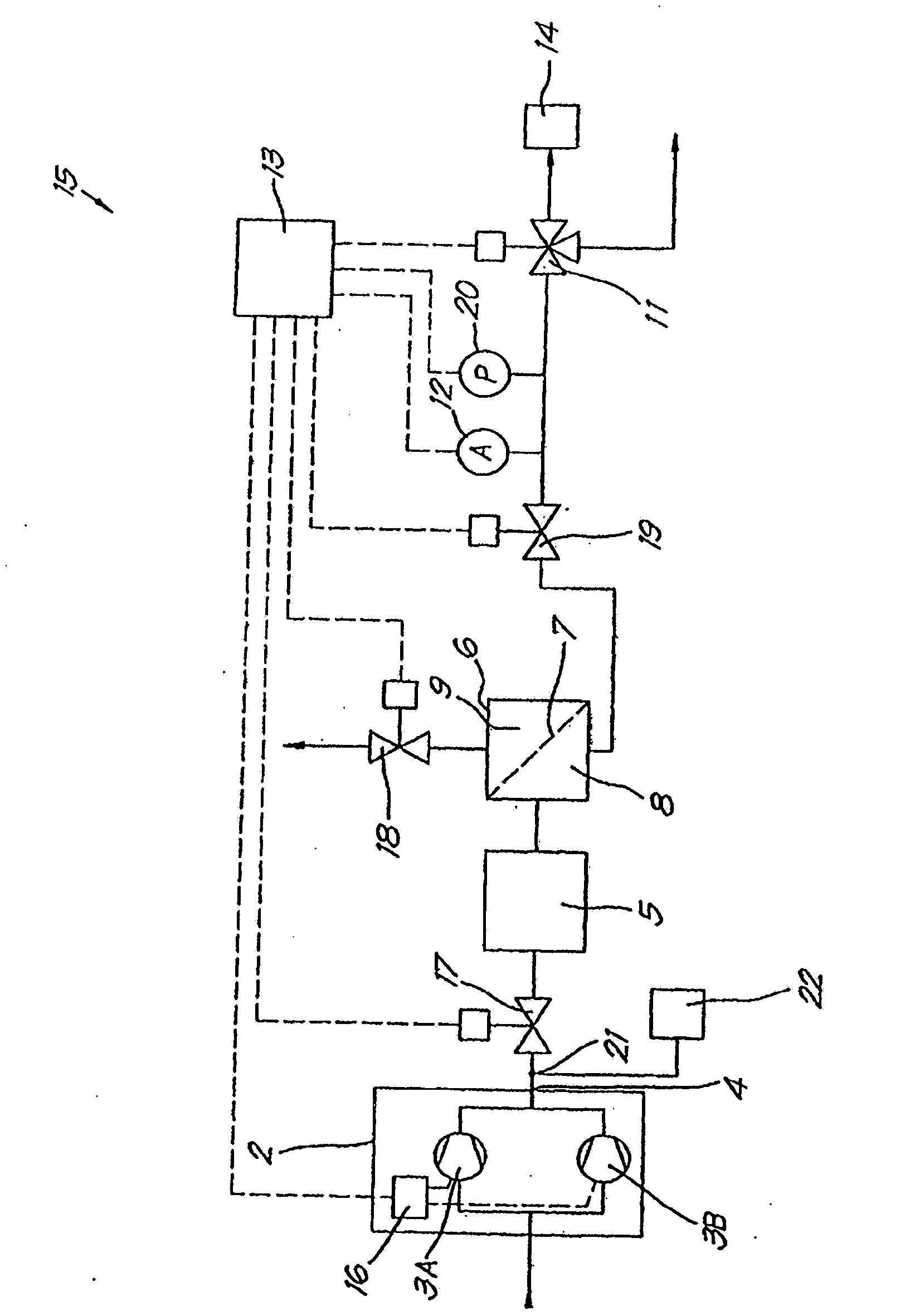
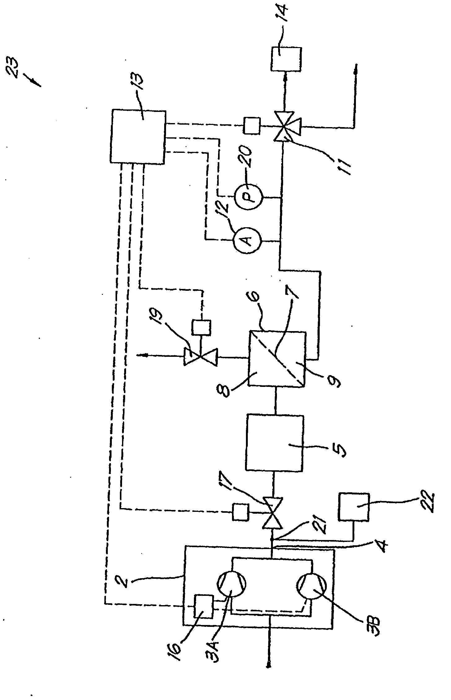
[0069] The plant 1 illustrated in Figure 1 is a plant for the production of nitrogen from air, whereby the nitrogen has a certain minimum purity.

[0070] The device 1 comprises a compressor unit 2 with a compressor 3, the outlet 4 of which is connected via a gas treatment unit 5 to a membrane unit 6 equipped with a membrane 7 whose permeability to oxygen higher than nitrogen. The membrane 7 separates the retentate side 8 from the permeate side 9 of the membrane unit 6 .

[0071] The compressor unit 2 may also include a gas dryer (not shown).

[0072] The stagnant side 8 is connected to a minimum pressure valve 10 and a three-way valve 11 . The oxygen sensor 12 is located between the minimum pressure valve 10 and the diaphragm unit 6 .

[0073] The oxygen sensor 12 is connected to the control unit 13 provided with an algorithm by means of signal transmission to adjust the capacity of the compressor in operation by means of a slide valve located at the inlet of the compresso...


PUM


Abstract

Device for separating gases that comprises the following components: a source for the gases and flow adjustment means; a membrane unit (6) for the production of a permeate gas and a retentate gas, one of which is the product gas; purity determining means for the product gas; a first control unit (13) for the device; a retentate control system (19) and a product gas pressure measurement, whereby the source has a second control unit (16) for the flow adjustment means as a function of a target value of the gases and the first control unit (13) is connected to the second control unit and to the retentate control system (19), whereby the first control unit (13) can determine the target value and can control the retentate control system (19).

Description

technical field [0001] The present application relates to devices and methods for separating gases. [0002] More specifically, the present invention relates to apparatus and methods for separating gas mixtures by means of membrane devices having selective membranes, ie membranes having different permeability to different gases based on their properties. Background technique [0003] The desired product may be permeate (ie, gas that has passed through the membrane wall) or retentate (ie, gas that has not passed through the membrane wall), as appropriate. [0004] Traditionally, such devices for separating gaseous mixtures consist of a compressor device in which the pressure of the feed gas, which is actually a gaseous mixture (for example, air) is increased, and a membrane device in which , the feed gas is separated into permeate and retentate gases such as oxygen and nitrogen. [0005] Because selective membranes are very expensive and constitute a large proportion of the...

Claims


Application Information

Patent Timeline
Patent Type & Authority Applications(China)
IPC IPC(8): B01D53/22C01B21/04
CPCB01D53/22B01D2311/14C01B21/0438B01D63/00B01D2053/221B01D2313/24
Inventor P·J·埃尔曼
Owner ATLAS COPCO AIRPOWER NV
Why Eureka
Try Eureka