Fundus camera optical system for aligning working positions of human eyes and position aligning method

A technology of working position and optical system, which is applied in the field of optoelectronics, can solve problems such as the inability to achieve precise alignment of the working position of the human eye

Active Publication Date: 2015-01-07
SHENZHEN CERTAINN TECH CO LTD
View PDF12 Cites 8 Cited by
  • Summary
  • Abstract
  • Description
  • Claims
  • Application Information

AI Technical Summary

Problems solved by technology

[0003] The present invention provides a fundus camera optical system and a position alignment method for precise alignment of the working position of the human eye. alignment problem

Method used


Image

  • Fundus camera optical system for aligning working positions of human eyes and position aligning method
  • Fundus camera optical system for aligning working positions of human eyes and position aligning method
  • Fundus camera optical system for aligning working positions of human eyes and position aligning method

Examples


Embodiment 1

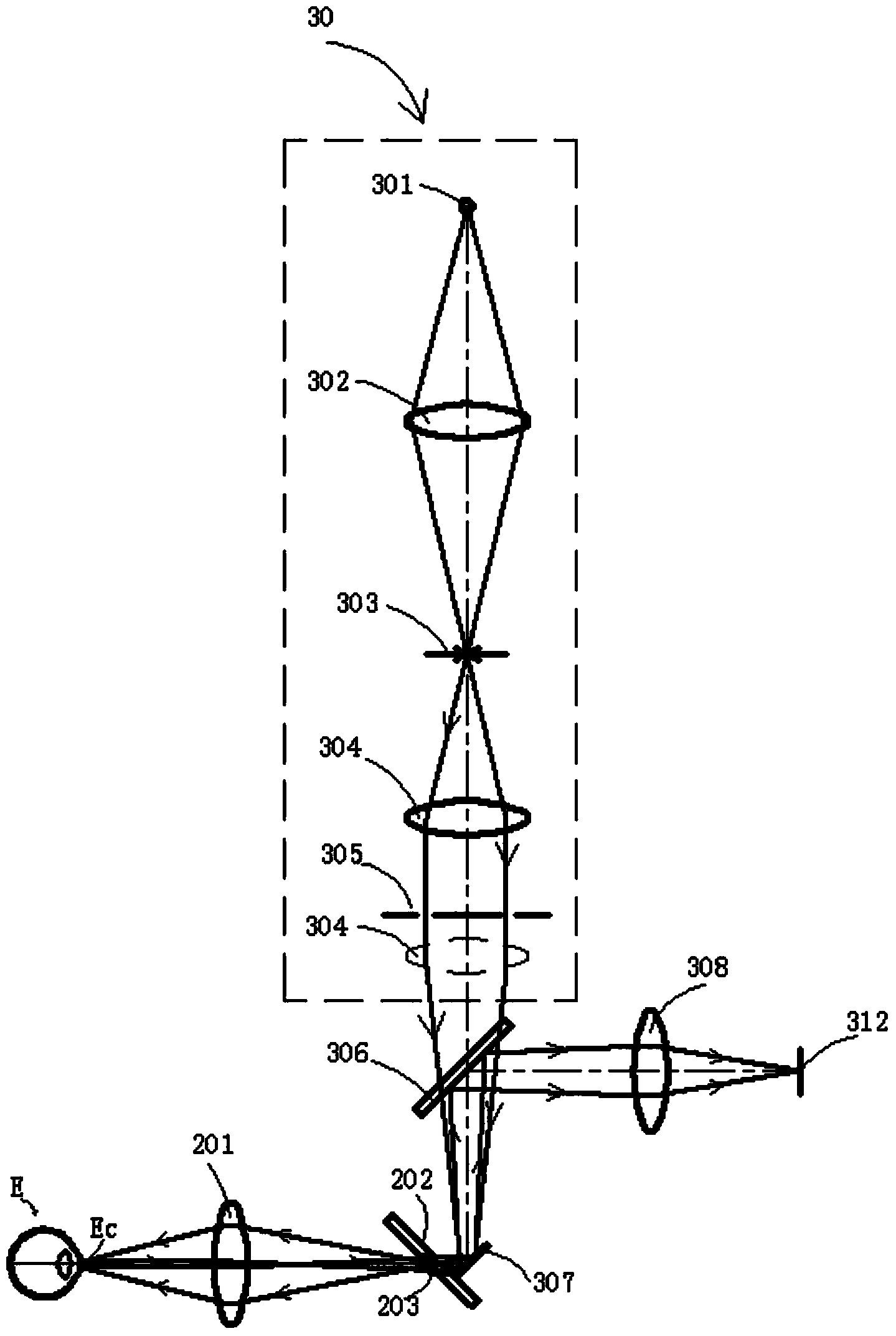
[0056] refer to figure 2 , figure 2 The optical system of the fundus camera includes alignment light path, illumination light path, imaging light path and gaze light path.

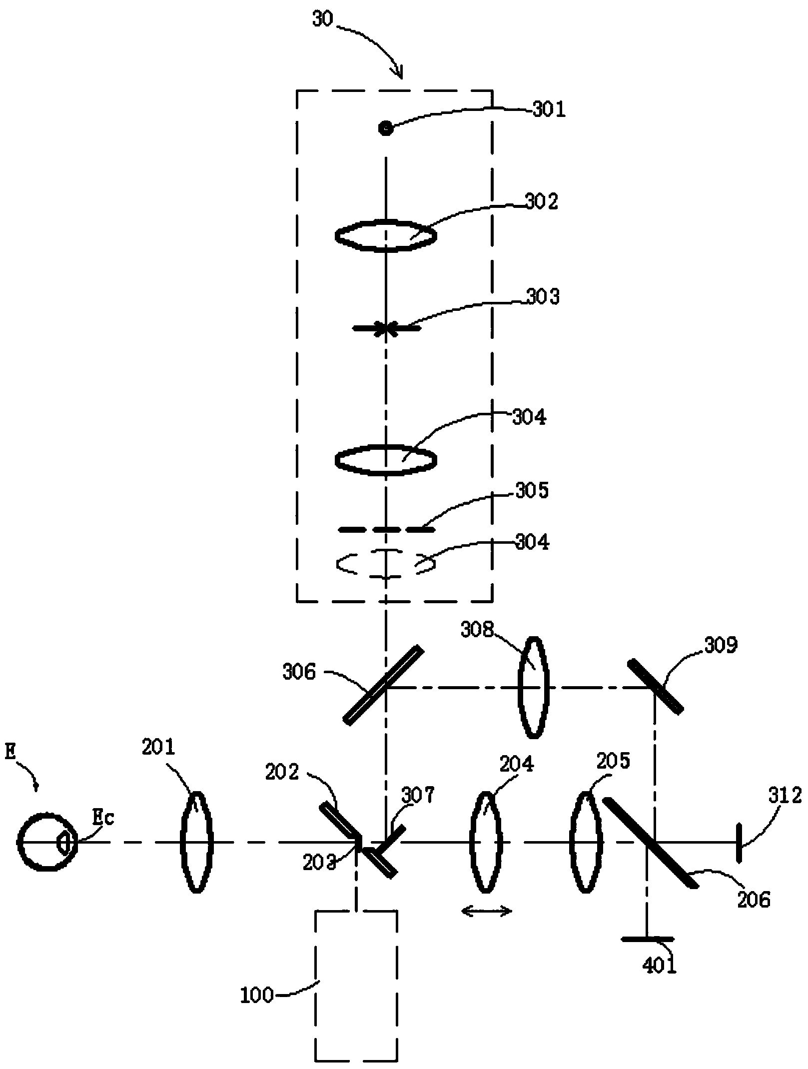
[0057] In this embodiment, aligning the optical path and figure 1 The difference in the alignment optical path is that a total reflection mirror 309 and a third beam splitter 206 are also provided between the receiving lens 308 and the camera device 312 . The total reflection mirror 309 reflects the first light beam and the second light beam reflected by the cornea from the receiving lens 308, and passes the first light beam and the second light beam to the third beam splitter 206. 312, the camera device 312 displays two superimposed light spots produced by focusing on the first light beam and the second light beam after the probe is adjusted. The observer can observe the two superimposed light spots. It is judged that the apex of the cornea is in the working position of the fundus camera.

[0058] I...

Embodiment 2

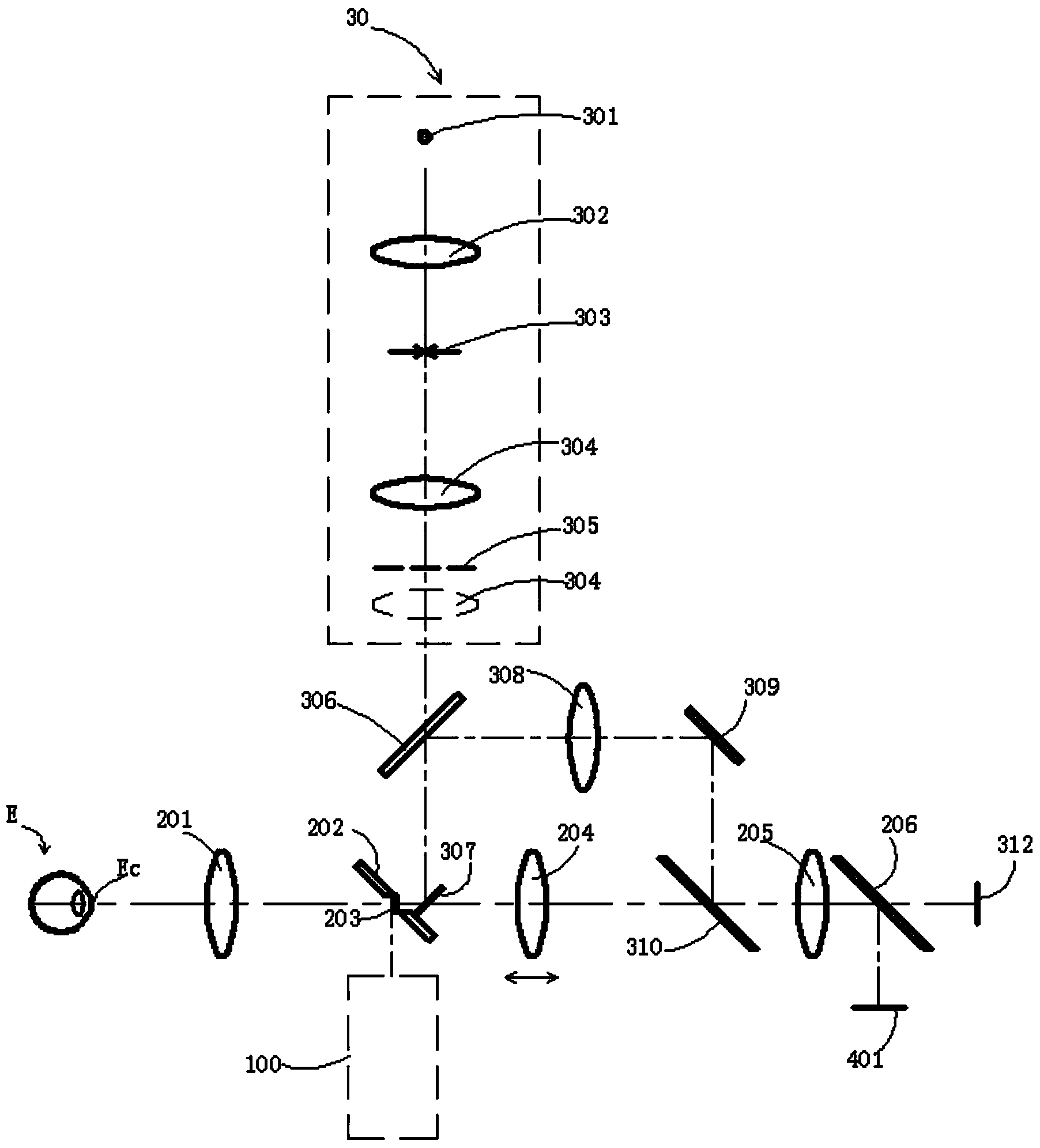
[0063] refer to image 3 The difference between this embodiment and the first embodiment is that a fourth dichroic mirror 310 is further provided between the deflection mirror 204 and the imaging lens 205 . The gazing light sent by the fixation point display screen 401 is reflected by the third beam splitter 206, passes through the imaging lens 205 successively, is fully transmitted through the fourth beam splitter 310, and then passes through the deflection mirror 204, the second beam splitter 307, and the embedded device. The aperture reflector 202 and the eye-connecting objective lens 201 of the first aperture diaphragm 203 reach the fundus of the human eye. Another function of the fourth beam splitter 310 in this embodiment is to fully reflect the first light beam and the second light beam from the total reflection mirror 309 after being reflected by the cornea.

[0064] Similarly, in this embodiment, the white light flash and near-infrared illumination light emitted by t...

Embodiment 3

[0068] refer to Figure 4 The difference between this embodiment and the first embodiment is that the imaging optical path of the fundus camera is divided into white light flash photography imaging and infrared preview fundus imaging. The white light flash photography imaging optical path is the same as that of the first embodiment, but the infrared preview fundus imaging optical path does not share the imaging device 207 .

[0069] In this embodiment, the propagation path of the alignment optical path is as follows: the first light beam and the second light beam generated by the double beam generating device 30 are partially transmitted through the first beam splitter 306, and then completely reflected by the second beam splitter 307, and the first beam and the second light beam pass through the first aperture diaphragm 203, and then enter the human eye through the eye lens 201, and are reflected by the cornea. After passing through the eye lens 201, the two emitted light bea...


PUM


Abstract

The invention discloses a fundus camera optical system for aligning working positions of human eyes and a position aligning method. The working principle of an aligning optical path is as follows: one parts of a first light beam and a second light beam which are generated by a double-beam generation device are reflected by a second beam splitter after passing through a first beam splitter, and the reflected parts are incident into the human eye via an eye objective lens after passing through a first diaphragm with a hole; the two light beams are reflected back by the corneal, passes through the eye objective lens and the first diaphragm with the hole and are incident into the second beam splitter and reflected by the second beam splitter to the first beam splitter; a probe is adjusted so that the two light beams are just gathered on an imaging device, and at the moment, the imaging device displays two spots which are overlapped on each other and generated by focusing the two light beams on the imaging device, and then the working position of the vertex of the corneal in a fundus camera is judged according to the two spots overlapped on each other. As the aligning optical path does not comprise a diopter lens, the alignment of the working position is not affected by refractive adjustment, and therefore, even for different human eyes, the vertex of the corneal in the fundus camera is well-determined.

Description

technical field [0001] The invention relates to the field of optoelectronics, in particular to a fundus camera optical system for aligning the working positions of human eyes. Background technique [0002] The fundus camera needs to maintain a precise distance between the human eye to be tested and the probe during the working process. However, in the prior art, because the optical path of the working position is determined through the system's deflection imaging optical path, when testing different human eyes, the deflection mirror The difference in position will inevitably lead to the difficulty of precise positioning of the working position, which will cause inaccurate test results. Contents of the invention [0003] The present invention provides a fundus camera optical system and a position alignment method for precise alignment of the working position of the human eye. Alignment issues. [0004] Technical scheme of the present invention: [0005] The fundus camera...

Claims


Application Information

Patent Timeline
Patent Type & Authority Applications(China)
IPC IPC(8): A61B3/15A61B3/12
Inventor 王辉蔡守东吴蕾何卫红
Owner SHENZHEN CERTAINN TECH CO LTD
Why Eureka
Try Eureka