Compressing mechanism for high-efficiency air filter

A compacting mechanism, high-efficiency air technology, applied in the fields of dispersed particle filtration, chemical instruments and methods, dispersed particle separation, etc., can solve the problems of reduced filter service life, uneven filter force, and reduced elasticity of sealing strips. , to achieve the effect of prolonging the service life, pressing and loosening the operation is simple and fast, and the pressing force is evenly distributed.

Inactive Publication Date: 2015-01-07
苏州安泰空气技术有限公司
View PDF9 Cites 1 Cited by
  • Summary
  • Abstract
  • Description
  • Claims
  • Application Information

AI Technical Summary

Problems solved by technology

[0004] However, the above-mentioned compression frame is only pushed and compressed by an eccentric machine located in the middle of the box, and the compression force is applied to the middle of the compression frame, which is two-point compression, and there is still unevenness in the stress on the filter, which has not been truly realized. The "surface" is compressed; at the same time, during long-term use, it is found that the elasticity of the sealing strip will gradually decrease, and the original compression force will not increase at the same time, so there will be a problem of reduced sealing performance, which will affect the filtering effect and need to be replaced in time , the service life of the filter is reduced and the cost is increased

Method used


Image

  • Compressing mechanism for high-efficiency air filter
  • Compressing mechanism for high-efficiency air filter
  • Compressing mechanism for high-efficiency air filter

Examples


Embodiment 1

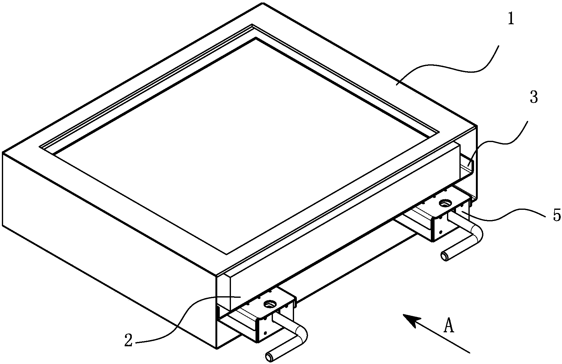
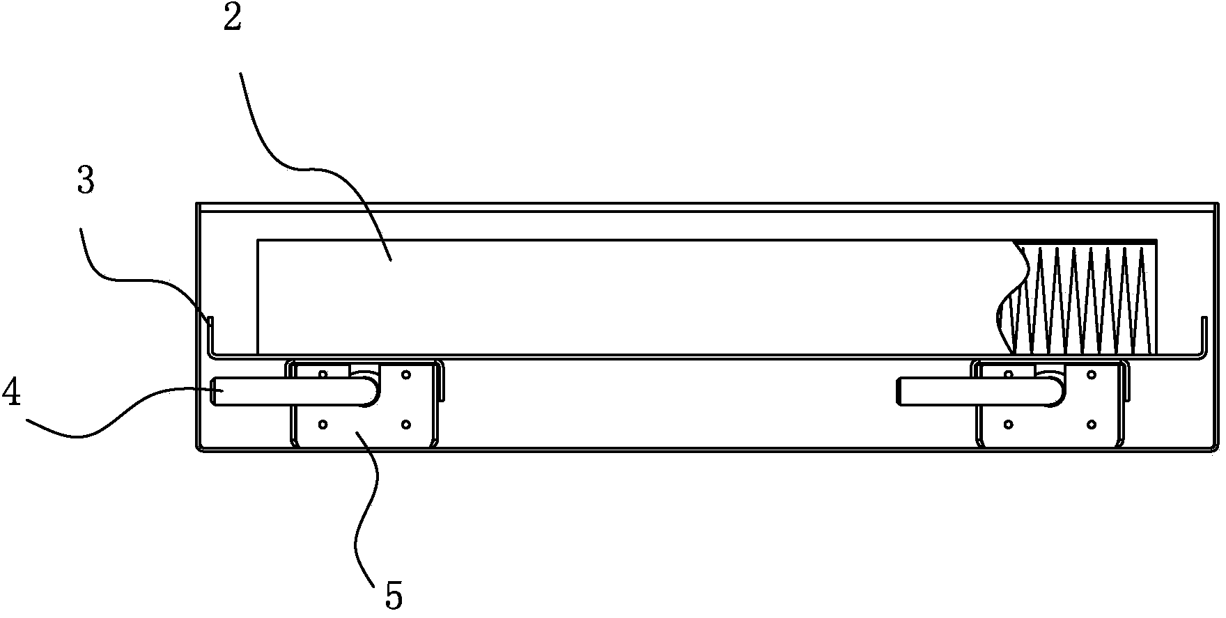
[0031] Embodiment one: see Figure 1~6 As shown, a high-efficiency air filter compression mechanism includes a box body 1 and a compression device arranged in the box body 1. The compression device includes two pre-tightening structures 5 and a pressure frame 3 carrying the filter 2. And four spring members 6 respectively located under the four corners of the pressure frame 3, the pre-tensioning structure 5 is located under the pressure frame 3, including a driving part and a pushing part connected with the driving part, and the pushing part is against the On the pressure frame 3, the pushing part has a degree of freedom to push the pressure frame 3 to move through the driving part, and the distance of the degree of freedom is matched with the gap between the filter 2 and the top cover of the box body 1; The elastic member 6 is arranged between the bottom of the box body 1 and the pressure frame 3 , and the distance between its free height and compressed height is greater than...

Embodiment 2

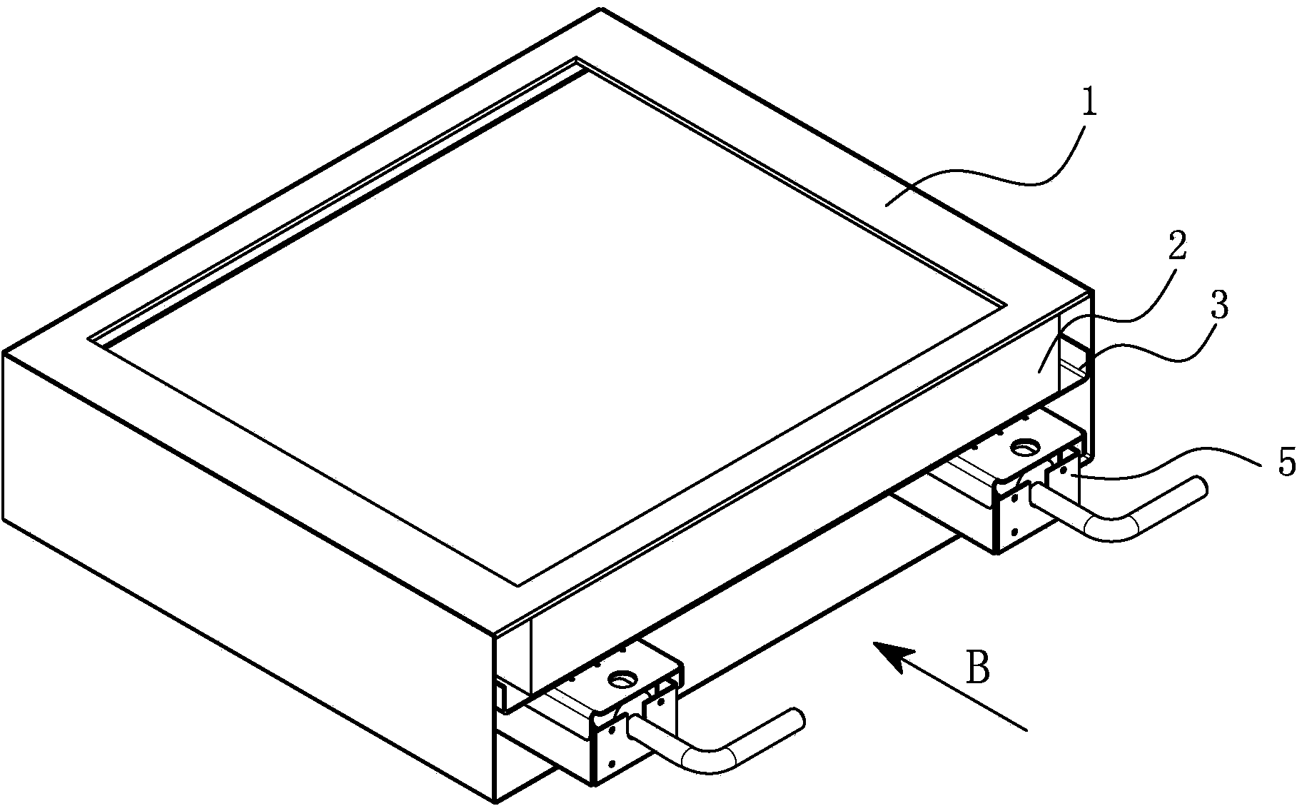
[0036] Embodiment two: see attached Figure 7-9 As shown, a high-efficiency air filter compression mechanism includes a box body 1, a compression device arranged in the box body 1, and the compression device includes a pre-tightening structure, a pressure frame 3 carrying a filter 2, and respectively Four spring members 6 located under the four corners of the pressure frame 3, the pre-tensioning structure is located under the pressure frame 3, including a driving part and a pushing part connected with the driving part, and the pushing part is against the pressure frame 3 Above, the pushing part has the degree of freedom to push the pressure frame 3 to move through the driving part, and the distance of the degree of freedom matches the gap between the filter 2 and the top cover of the box body 1; the elastic member 6 It is arranged between the bottom of the box body 1 and the pressure frame 3, and the distance between its free height and compressed height is greater than the fr...


PUM


Abstract

The invention discloses a compressing mechanism for a high-efficiency air filter. The compressing mechanism for the high-efficiency air filter comprises a box body and a compressing device which is arranged in the box body, and is characterized in that the compressing device comprises at least one pre-tightening structure, a pressing frame for bearing a filter, and a plurality of compensating elastic pieces which are respectively positioned below the four corners of the pressing frame, wherein the pre-tightening structure is positioned below the pressing frame and comprises a driving part and a pushing part which is connected with the driving part; the pushing part prop against the pressing frame, and has the freedom degree for pushing the pressing frame to move through the driving part; the freedom degree distance is in clearance fit with a gap between the filter and the top cover of the box body; the compensating elastic pieces are arranged between the bottom of the box body and the pressing frame; the distance between the freedom degree and the compression height is greater than the freedom degree distance of the pushing part. According to the compressing mechanism for the high-efficiency air filter, the surface compression is realized through the arrangement and the distribution of compensation elasticity; pressing force is provided durably; the sealing performance is guaranteed; the service life is prolonged.

Description

technical field [0001] The invention relates to the field of air purification technology and devices, in particular to a high-efficiency air filter compression mechanism. Background technique [0002] High-efficiency air filters are mainly used to capture particles, dust and various suspended solids above 0.3 microns. They use ultra-fine glass fiber paper as the filter material, and are glued with the outer frame (aluminum alloy or aluminum plate, etc.), and are widely used in optical electronics. , LED liquid crystal manufacturing, PCB printing, biomedicine, precision instruments, beverages and food and other industries dust-free purification workshop air-conditioning terminal air supply. If the filter is not installed reliably, polluted air may be directly discharged through the installation leakage point, endangering environmental safety or affecting indoor cleanliness, so the sealing between the filter element and the outer frame in the filter is very important. At the ...

Claims


Application Information

Patent Timeline
Patent Type & Authority Applications(China)
IPC IPC(8): B01D46/42
Inventor 吴志坚江尧姚晓敏马建惠
Owner 苏州安泰空气技术有限公司
Why Eureka
Try Eureka