Thin-walled cylindrical part end face machining fixture

A technology of end face processing and thin-walled cylinder, which is applied in the direction of manufacturing tools, metal processing equipment, metal processing machinery parts, etc., can solve the problems of difficult maintenance and replacement, complicated installation, increased scrap rate, etc., and achieves convenient clamping operation, The effect of easy maintenance and replacement, reducing scrap rate

Active Publication Date: 2015-01-07
CHINA NTAIONAL NUCLEAR TIANJIN MACHINERY
View PDF6 Cites 11 Cited by
  • Summary
  • Abstract
  • Description
  • Claims
  • Application Information

AI Technical Summary

Problems solved by technology

The disadvantage of manual clamping device is that the labor intensity of the operator is high and the labor productivity is low; the automatic expansion core clamp is more complicated to install and more difficult to maintain and replace.
[0003] Moreover, the current expansion core clamping structure also has many problems in terms of structure and use.
Since the thin-walled cylindrical parts to be processed are relatively long, in order to ensure that the thin-walled cylindrical parts are tightened, the expansion core should be lengthened accordingly. The extended core is prone to trembling during processing, resulting in the processing of thin-walled cylindrical parts. increased scrap rate
The main material of the expansion core clamping structure is harder than the material of the processed thin-walled cylindrical parts, which often causes the processed thin-walled cylindrical parts to deform and damage the workpiece

Method used


Image

  • Thin-walled cylindrical part end face machining fixture
  • Thin-walled cylindrical part end face machining fixture

Examples


Embodiment Construction

[0020] Hereinafter, the present invention will be described in detail with reference to the drawings and embodiments:

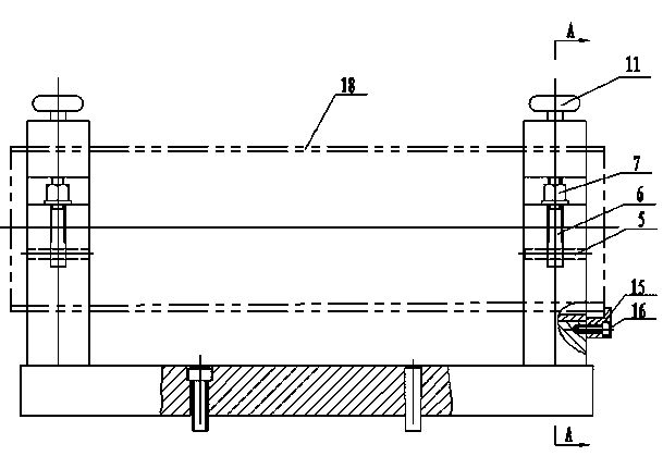
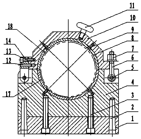
[0021] Such as figure 1 , 2 As shown, an end face machining fixture for thin-walled cylindrical parts includes a bottom plate 1. A parallel support base 4 is fixed on the base plate 1 through a bottom plate conical pin 2 and a bottom plate screw 3, and the upper end surface of the support base 4 is hinged with a connecting ring 14. A pin shaft 5 is provided on the other side. The connecting ring 14 is connected to the side wall of the gland 10 through the gland cone pin 12 and the gland screw 13. The pin shaft 5 is sheathed with a joint bolt 6, and the joint bolt 6 is locked The nut 7 presses the gland 10 onto the support base 4. In the groove formed by the joint ends of the support base 4 and the gland 10, a lower positioning sleeve 17, an upper positioning sleeve 8, and a lower positioning sleeve 17, an upper positioning sleeve are fixed by screws 9 respectivel...


PUM


Abstract

The invention discloses a thin-walled cylindrical part end face machining fixture which comprises a bottom plate. Parallel supporting seats are fixed onto the bottom plate through bottom plate taper pins and bottom plate screws, a connecting ring is hinged to one side of the upper end face of each supporting seat, a pin is arranged on the other side of the upper end face of each supporting seat, each connecting ring is connected with the side wall of a pressing cover through a pressing cover taper pin and a pressing cover screw, hinged bolts sleeve the pins, the pressing covers are pressed on the supporting seats through locking nuts on the hinged bolts, and a lower positioning sleeve and an upper positioning sleeve are fixed into grooves formed by the supporting seats and the pressing covers through screws respectively and combined to form a continuous cylindrical positioning sleeve. A thin-walled cylindrical part is radially positioned by the upper positioning sleeve and the lower positioning sleeve which are parallel, the thin-walled cylindrical part is axially positioned by positioning blocks on the side walls of the supporting seats, the thin-walled cylindrical part end face machining fixture is convenient in clamping operation, high in efficiency and convenient to detach, maintain and replace, shaking of a workpiece to be machined in the machining process is avoided, and rejection rate is reduced.

Description

Technical field [0001] The invention belongs to a processing fixture for parts, in particular to a processing fixture for the end face of thin-walled cylindrical parts. Background technique [0002] At present, the turning fixtures for thin-walled cylindrical parts mainly adopt manual clamping and automatic expansion core clamping. The disadvantages of the manual clamping device are that the operator's labor intensity is high and the labor productivity is low; the automatic core expansion fixture is more complicated to install and difficult to repair and replace. [0003] Moreover, the current expansion core clamping structure also has many problems in terms of structure and use. Since the processed thin-walled cylindrical parts are relatively long, in order to ensure that the thin-walled cylindrical parts are tightened, the expansion core should be correspondingly lengthened. The elongated expansion core is prone to tremor during the processing, resulting in the processed thin-wa...

Claims


Application Information

Patent Timeline
Patent Type & Authority Applications(China)
IPC IPC(8): B23Q3/06
CPCB23Q3/065
Inventor 孙岳城刘敬王世喆胡勇董浩孔令超
Owner CHINA NTAIONAL NUCLEAR TIANJIN MACHINERY
Why Eureka
Try Eureka