Magnetic punch

A stamping machine and magnetic technology, applied in the field of automation equipment, can solve the problems of high purchase and use costs, large power consumption, and large vibrations, and achieve the effects of low equipment production costs, low use costs, and low power consumption

Inactive Publication Date: 2015-01-07
苏州艾虎数码科技有限公司
View PDF8 Cites 4 Cited by
  • Summary
  • Abstract
  • Description
  • Claims
  • Application Information

AI Technical Summary

Problems solved by technology

Although these punching machines have a strong impact force and can cause a large amount of deformation to the raw steel plate, the use of this kind of punching machine is also very limited, and the raw steel plate needs to be strongly fixed, and the vibration during the impact process is also Larger, this kind of traditional punching machine has a more complicated structure, higher power consumption, and higher purchase and use costs. Moreover, when this kind of punching machine is in production, the design of the jig for putting in and taking out raw materials is more complicated. It is not easy to improve the production efficiency of the assembly line

Method used


Image

  • Magnetic punch
  • Magnetic punch
  • Magnetic punch

Examples


Embodiment Construction

[0013] Below in conjunction with embodiment the present invention is further described:

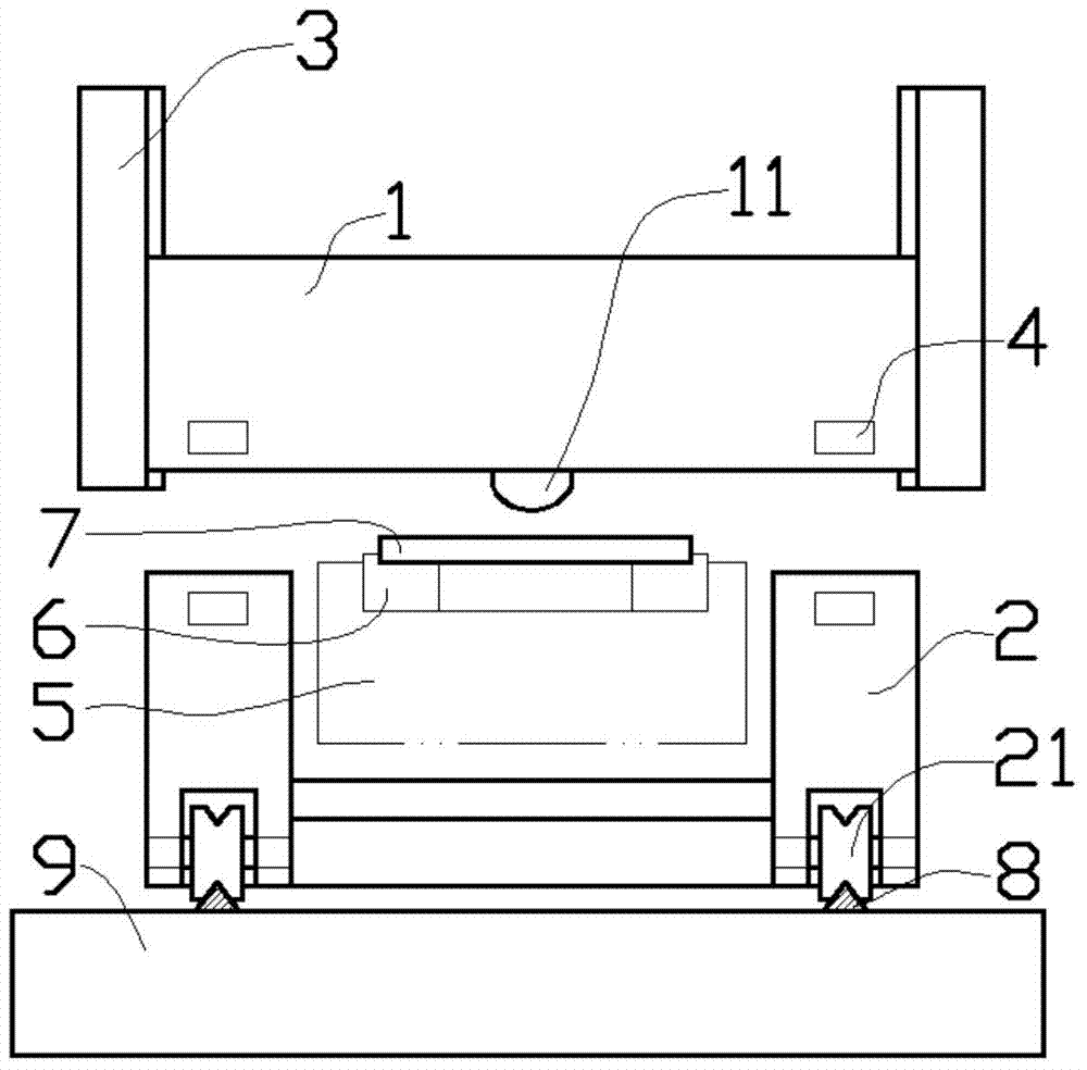
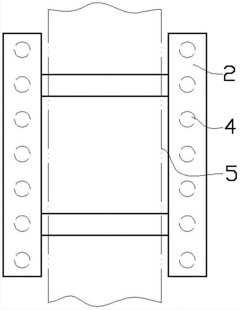
[0014] Such as figure 1 , figure 2 with image 3 As shown in the embodiment, the magnetic stamping machine includes a stamping block 1 and a magnetic trolley 2; the stamping block 1 is in a rectangular shape, and the two sides of the stamping block 1 are limited by vertical limit columns 3, and the The cross-section of the spacer post 3 can be designed as a trapezoid, and two of them are respectively assembled on each side of the both sides of the stamping block 1, so that the stamping block 1 can only slide vertically up and down. The two sides of the lower part of the stamping block 1 are fixed with small magnetic blocks 4 with vertical magnetic force lines, and the direction of the magnetic force lines of adjacent small magnetic blocks 4 on each side of the stamping block 1 is vertically opposite. The small magnetic blocks 4 on the side are symmetrically arranged, and the magnetic ...


PUM


Abstract

The invention provides a magnetic punch. The magnetic punch comprises a punching block and a magnetic cart; the punching block is rectangular; the two sides of the punching block are limited by use of limiting columns in the vertical direction; small magnetic blocks of which the magnetic lines of force are vertical are fixed on the two sides of the lower part of the punching block; the magnetic lines of force of every two adjacent small magnetic blocks on each side of the punching block are opposite in the vertical direction; the magnetic cart is arranged on the lower part of the punching block; small magnetic blocks corresponding to the lower part of the punching block in position are fixed on the upper parts of the two side edges of the magnetic cart, respectively; conveying lines are designed to penetrate through the middle positions of the two sides of the magnetic cart under the punching block; raw material plates are assembled on the upper parts of the conveying lines by use of punching templates. The magnetic punch is characterized in that magnetic force is provided for the punching block as punching force; the magnetic punch is simple in structure and low in cost; the magnetic force comes from permanent magnets, and therefore, the power consumption is lower and the use cost is low.

Description

Technical field [0001] The invention involves the field of automation equipment technology, which specifically involves a magnetic stamping machine. Background technique [0002] The traditional stamping machine is driven by the motor to drive the flywheel, and through the clutch, the transmission gear drives the crank connecting mechanism to move the slider up and down, and drive the stretch mold to the steel plate.Although these stamping machines have a strong impact, they can cause a large deformation to the raw material steel plate, but the use limit of this stamping machine is also very large.Larger, this traditional stamping machine structure is relatively complicated, the power consumption is large, the purchase and use costs are relatively high, and when the punching machine is produced, the design of the raw materials and the removal of the removal of the proportion is more complicated.It is not easy to improve the production efficiency of the assembly line.In the proces...

Claims


Application Information

Patent Timeline
Patent Type & Authority Applications(China)
IPC IPC(8): B30B1/42B21D22/02
CPCB21D22/02B30B1/42
Inventor 黄俊
Owner 苏州艾虎数码科技有限公司
Why Eureka
Try Eureka